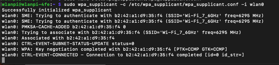
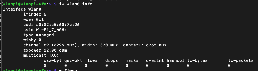
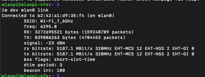
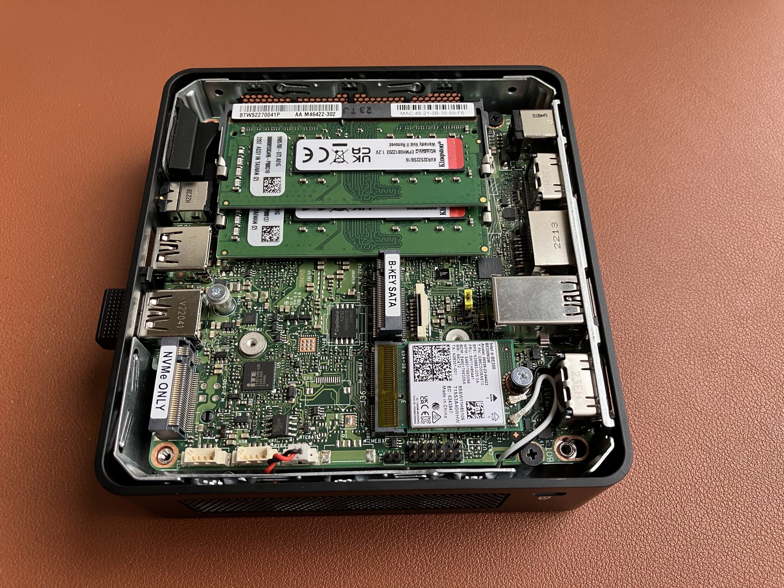
The other week I tested Wi-Fi 7 on Linux. It worked great. Let’s see how Intel BE200 Wi-Fi 7 adapter performs on Windows 11 23H2.
Drivers
Download and install latest driver from Intel’s website. Windows Update itself won’t install any driver, so some manual steps are required. I originally tested driver version 23.20.0.4, and now updated to 23.30.0.6.
Setup
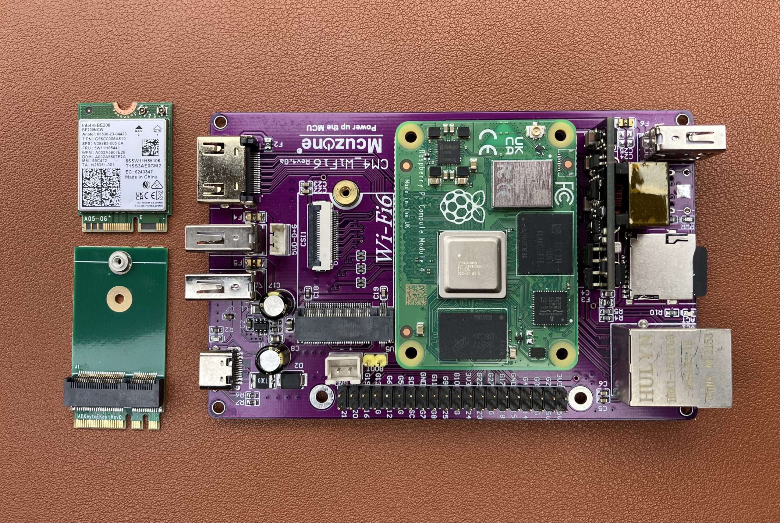
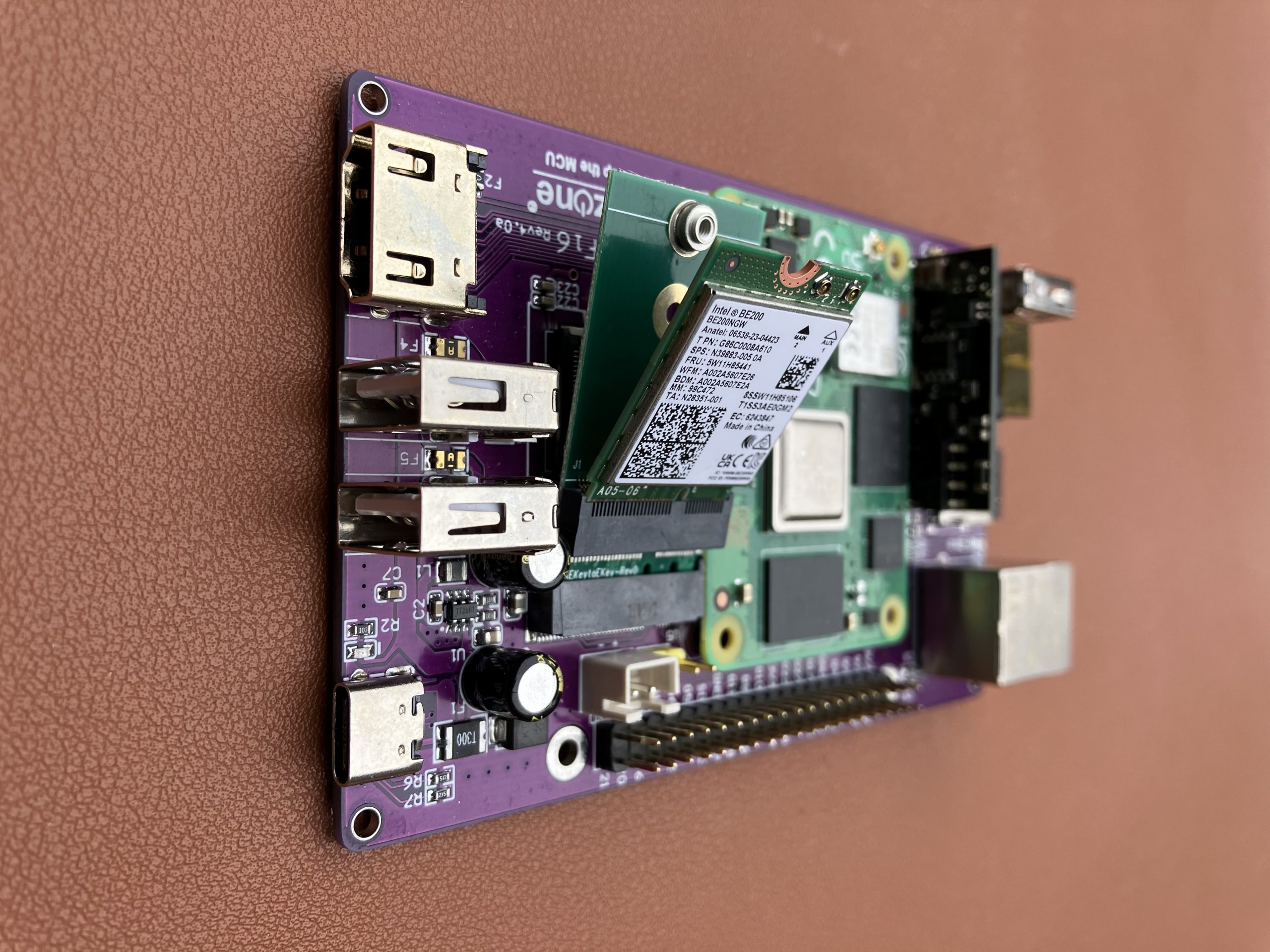
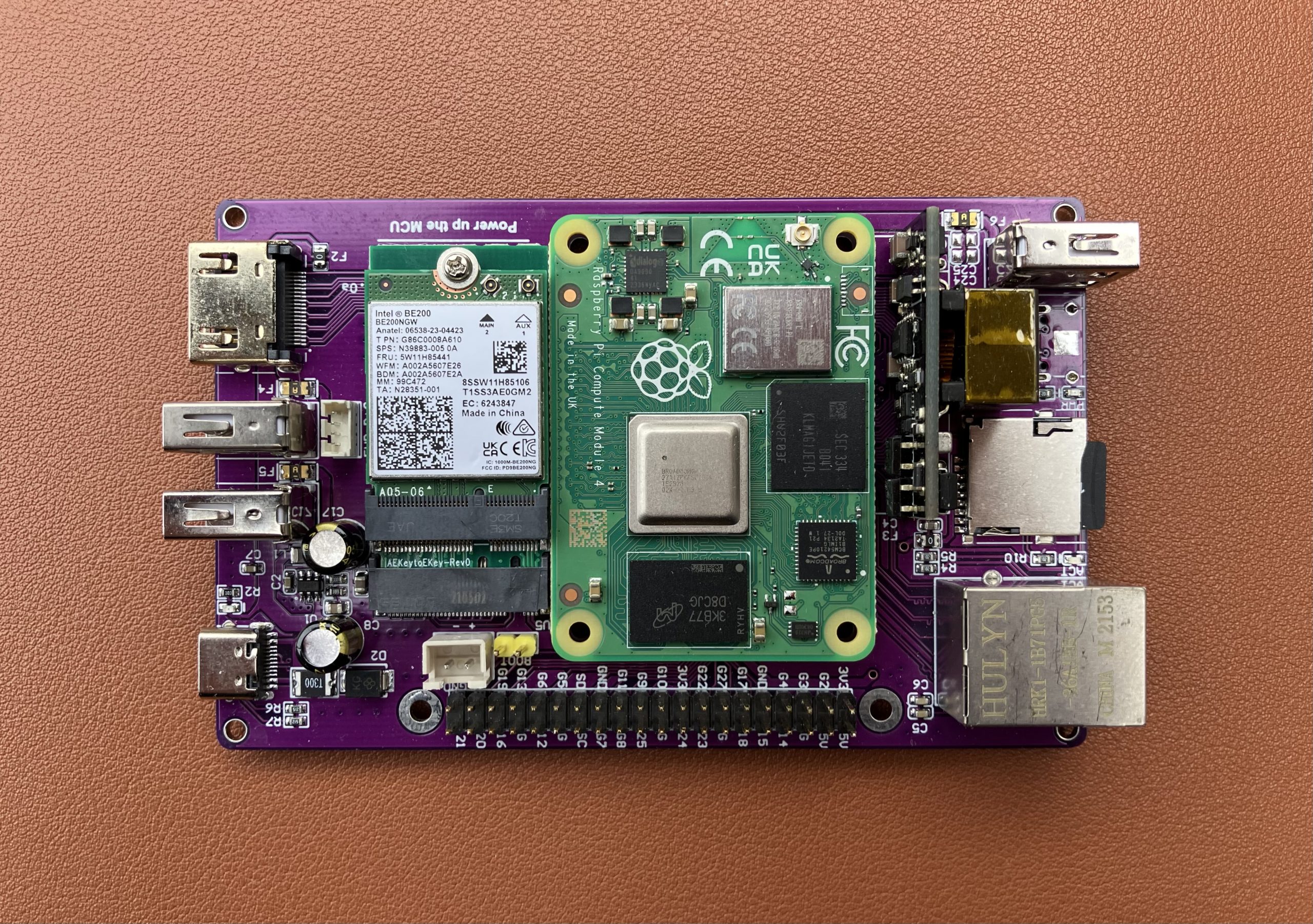
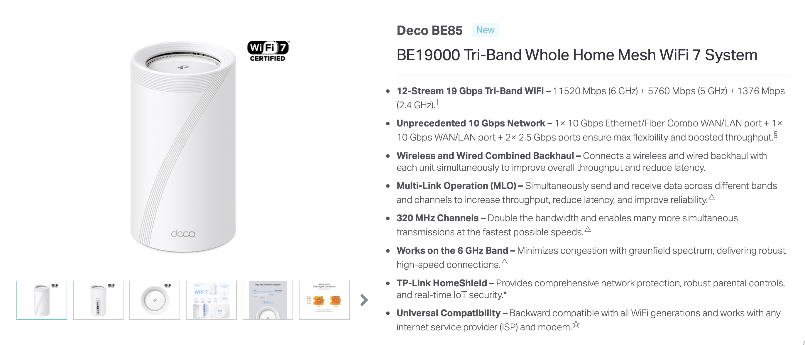
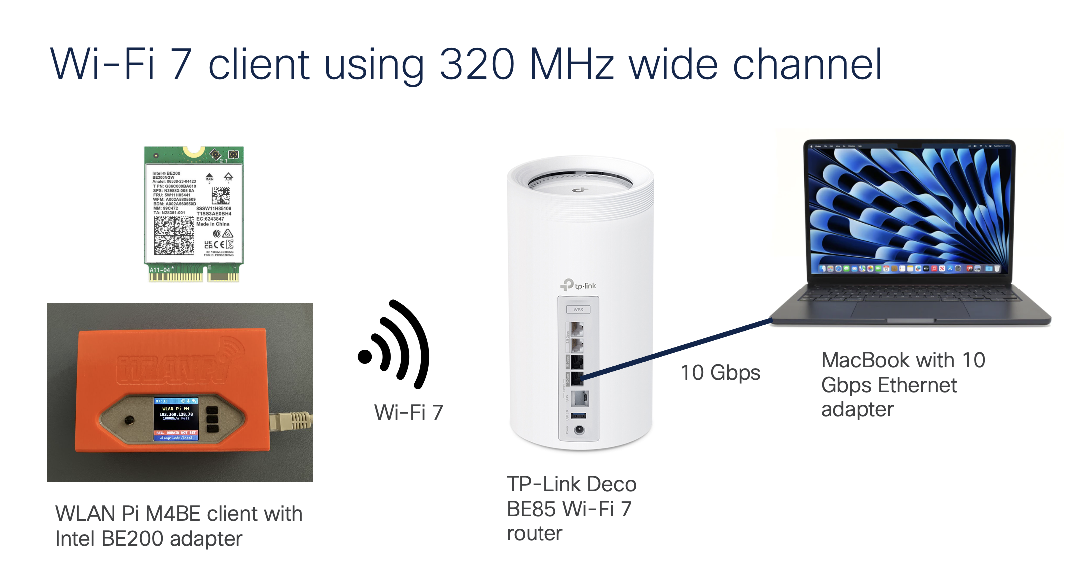
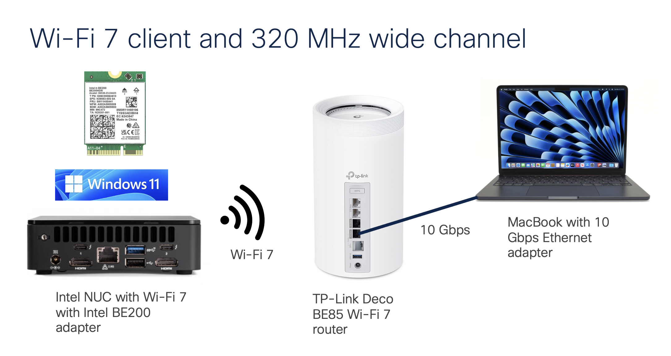
We are using TP-Link Deco BE85 BE19000 consumer Wi-Fi 7 router connected to a 10 Gigabit iperf3 server running on MacBook connected via OWC 10 GbE to Thunderbolt adapter. We have done this on Linux before, so let’s see how the same Wi-Fi adapter performs on Windows.
Performance
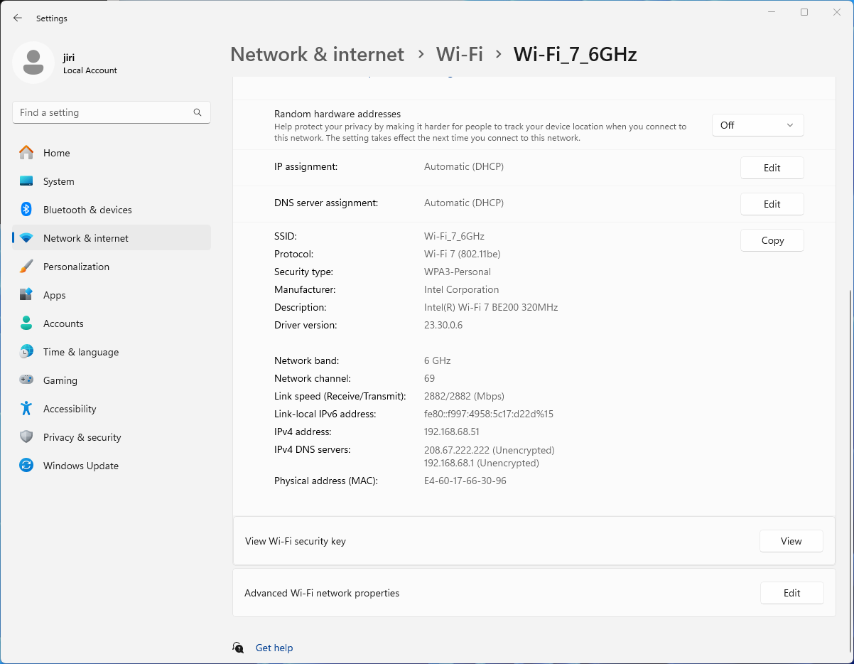
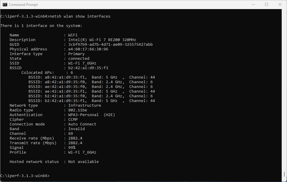
On the router, we have configured and verified 320 MHz wide Wi-Fi 7 channel. But when we connect the Windows client, looking at the data rate, it is surprisingly low – if you forgive me calling 2882 Mbps ‘low’ 😊 Considering that the NUC is about 1 meter away from the router, I would expect ~5 Gbps data rate. So what’s going on here?
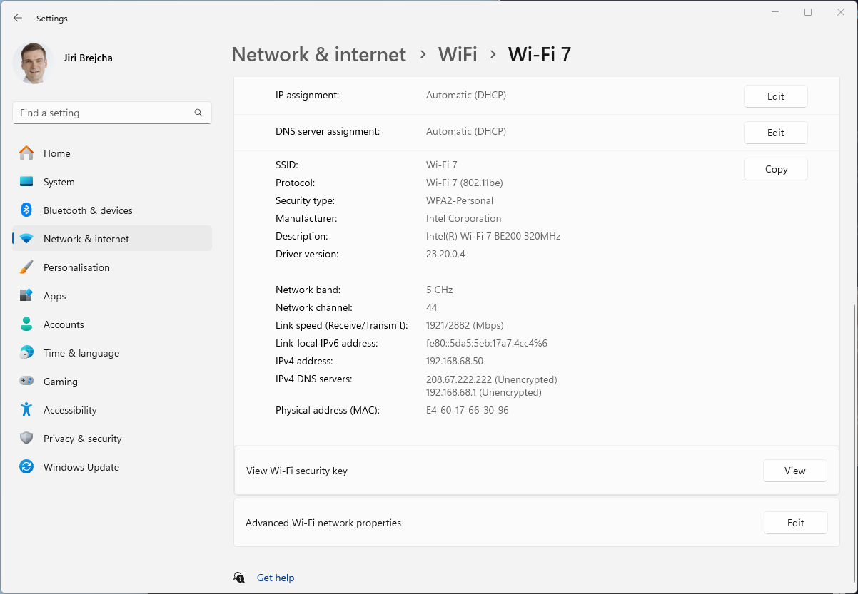
Interestingly enough, it is the same data rate as we see when connected using 5 GHz 160 MHz channel. Yes, I know, that’s a no-no in Wi-Fi design. We are just testing here.
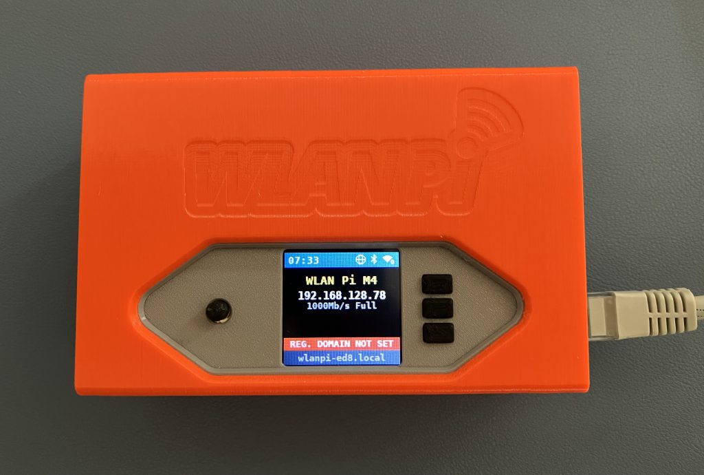
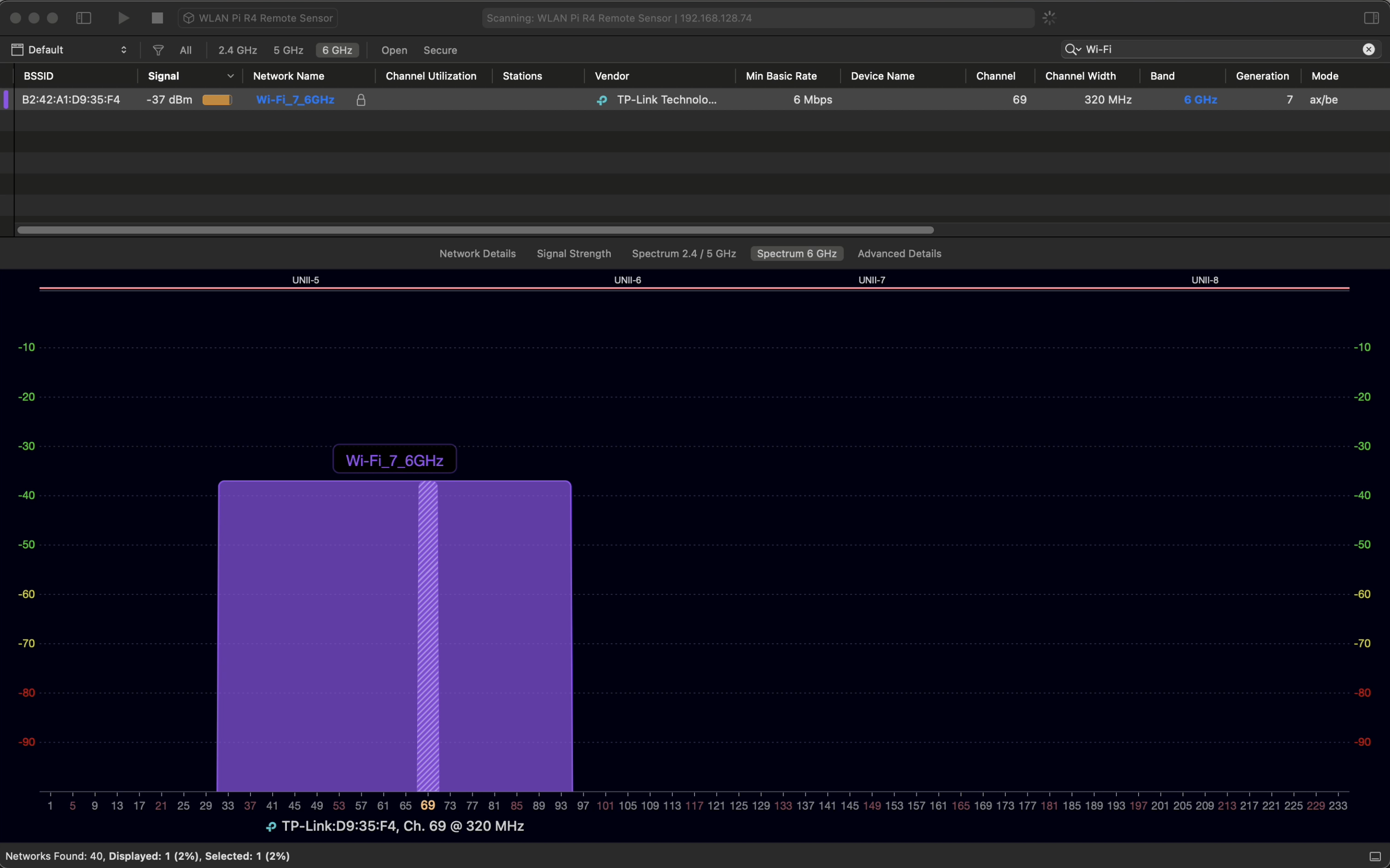
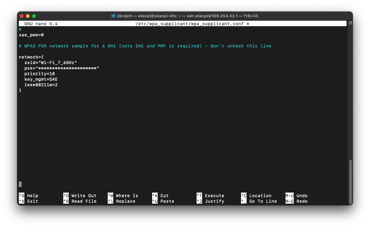
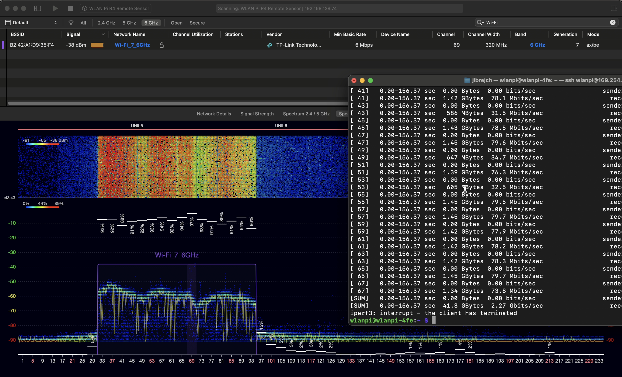
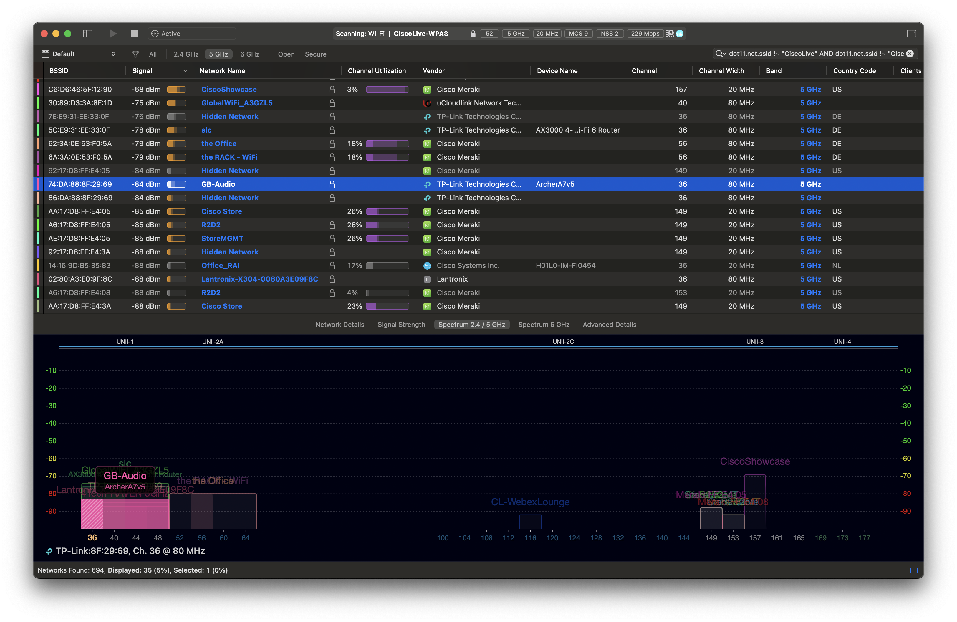
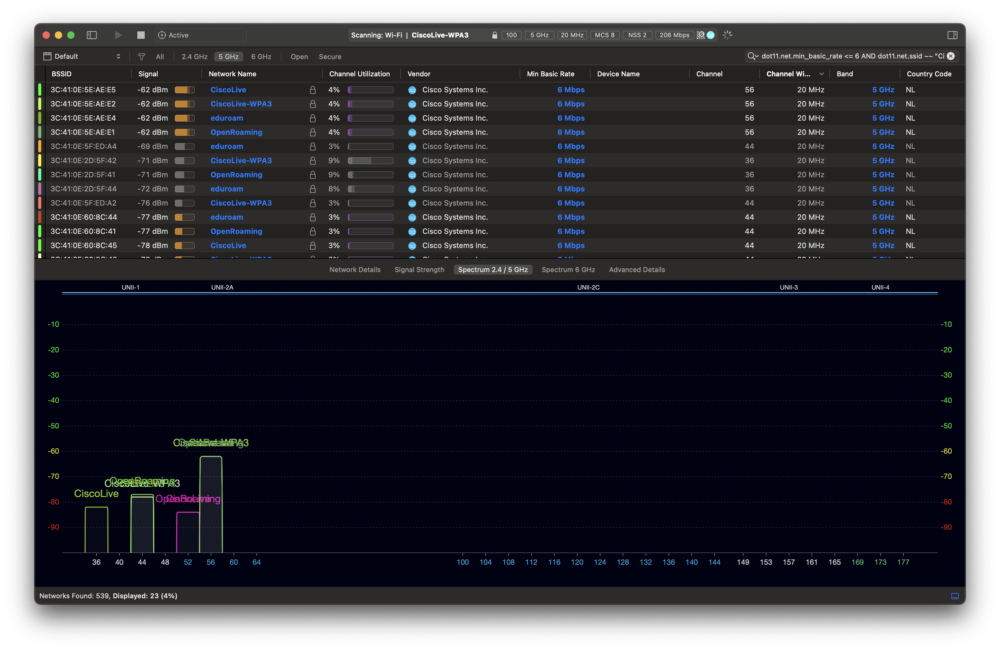
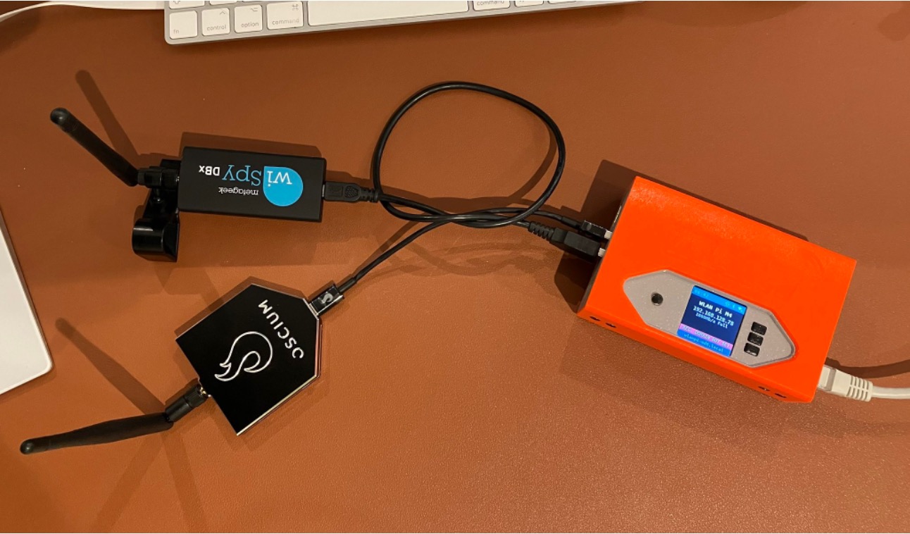
Since Windows doesn’t expose the channel width in the UI, we don’t quite know what is happening on the air. Let’s generate some 6 GHz traffic, and check using Oscium’s WiPry Clarity tri-band spectrum analyser. I love this little USB tool. In this example I use a WLAN Pi as a Remote Sensor. It scans for Wi-Fi networks and streams spectrum information to WiFi Explorer Pro on Mac.

Bingo! Apparently, on Windows Intel BE200 uses 160 MHz channel width and doesn’t support 320 MHz wide channel. That halves our data rate and throughput. I wish Windows made channel width more obvious in the UI. Intel BE200 adapter supports 320 MHz wide channels on Linux without a sweat, so hopefully it will get fixed in a future Intel driver or Windows release.
Updated: Apparently, I didn’t read Intel’s release notes closely enough, my bad 😊 Intel BE200 adapter on Windows 11 is only able to use Wi-Fi 6E today. Windows 11 will introduce Wi-Fi 7 support in a future update. Since Wi-Fi 6E supports channel widths up to 160 MHz, that’s why we are not being able to use full 320 MHz channel width. What really confused me was the “Protocol: Wi-Fi 7 (802.11be)” misleading Wi-Fi network status reported by Windows. Thank you Ben for spotting the note in Intel’s documentation.
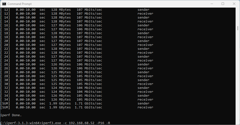
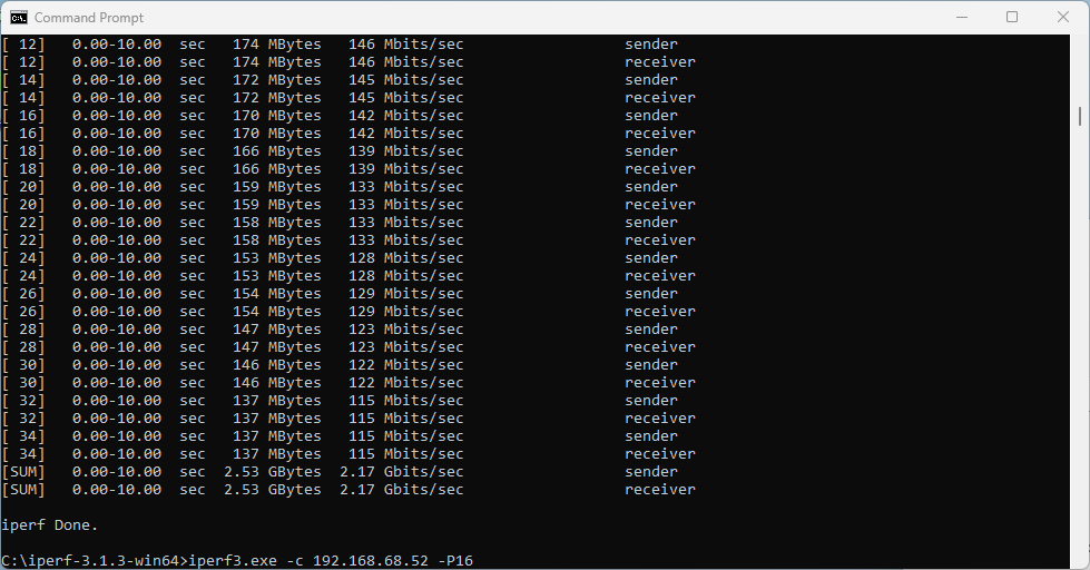
What does that translate to? Lower data rate and lower throughput. I would expect download and upload to be around 2.5 Gbps using 320 MHz wide channel. With the latest Intel driver 23.30.0.6, we get 1.71 Gbps TCP download speed with 16 parallel streams, and upload of 2.17 Gbps. But only the upper 160 MHz half of the 320 MHz wide channel is used.
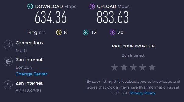
I also ran a quick Speedtest.net test (I know it is not a proper throughput testing tool) on a 900/900 Mbps WAN link.
On a Linux Wi-Fi 7 client, I measured nearly 890/890 Mbps. Original Intel driver 23.20.0.4 performed 383/818 Mbps. The latest Intel driver 23.30.0.6 delivered more symmetric numbers, and results were closer to the actual WAN link speed.
Summary
Wi-Fi worked well, but application speeds including Speedtest.net and other tools performed quite poorly and subjectively ‘felt slow’. iperf3 test showed higher performance, but the main problem for the purpose of a throughput test is that the adapter only uses 160 MHz out of the available 320 MHz.
When it comes to recommended channel width in real world, it depends. 80 MHz or 40 MHz wide channels are most likely the best place to start depending on your circumstances and region.
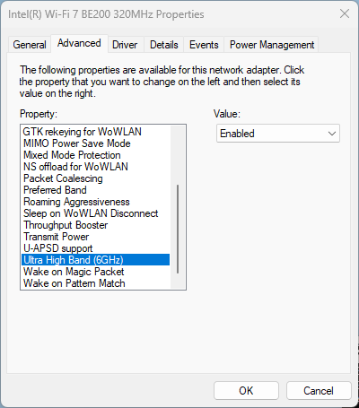
For reference: Disable 6 GHz on Intel BE200 adapter
If you are performing tests on an SSID that has multiple bands enabled, and you want to force the client to drop off 6 GHz and join using a 5 GHz channel instead, Intel BE200 driver has the option to disable the 6 GHz band.