Earlier this week, I tested a 10 Gigabit Ethernet M.2 network adapter on Raspberry Pi 5, and it didn’t quite cut it. Mainly due to limited PCIe Gen 2 performance. Now, the question is can this 10 Gigabit adapter actually push 10 Gbps of traffic at all?
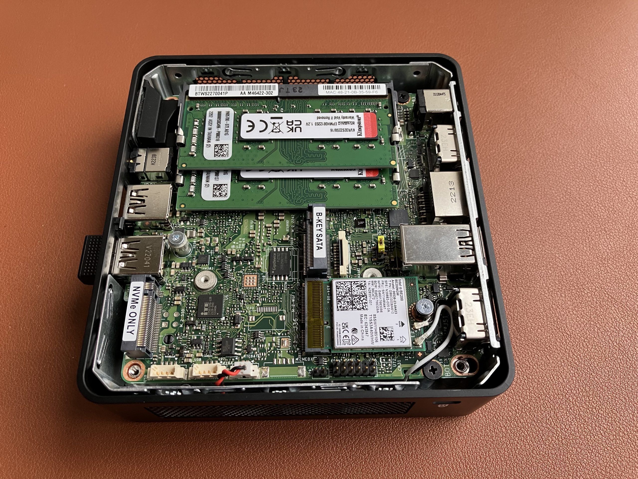
To find out, we are going to slightly reconfigure this Intel NUC 12th generation mini PC. It has an M.2 M-key slot for NVMe drive. Let’s use this slot for our 10 GbE adapter. And we will boot Windows 11 off an external USB SSD drive.
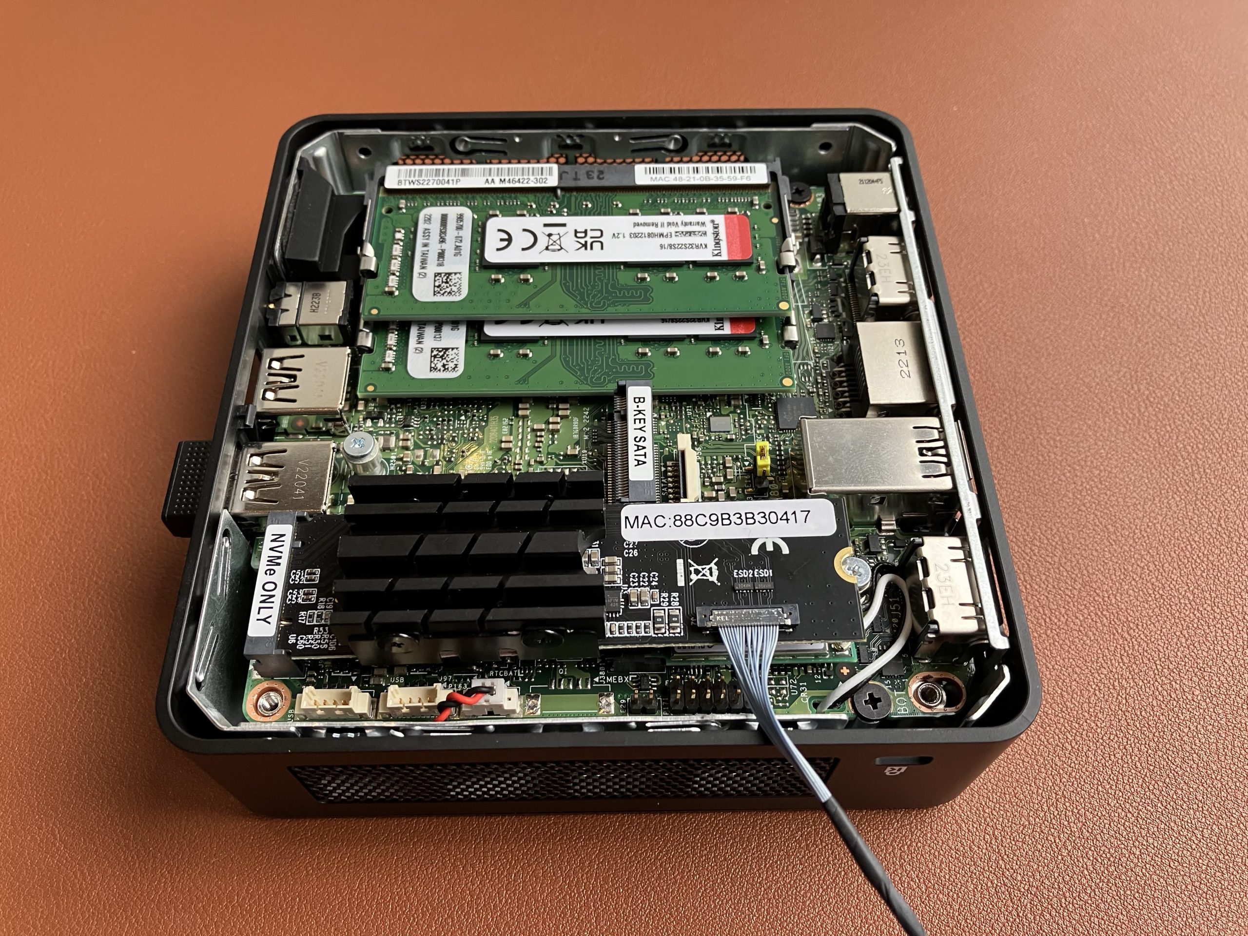
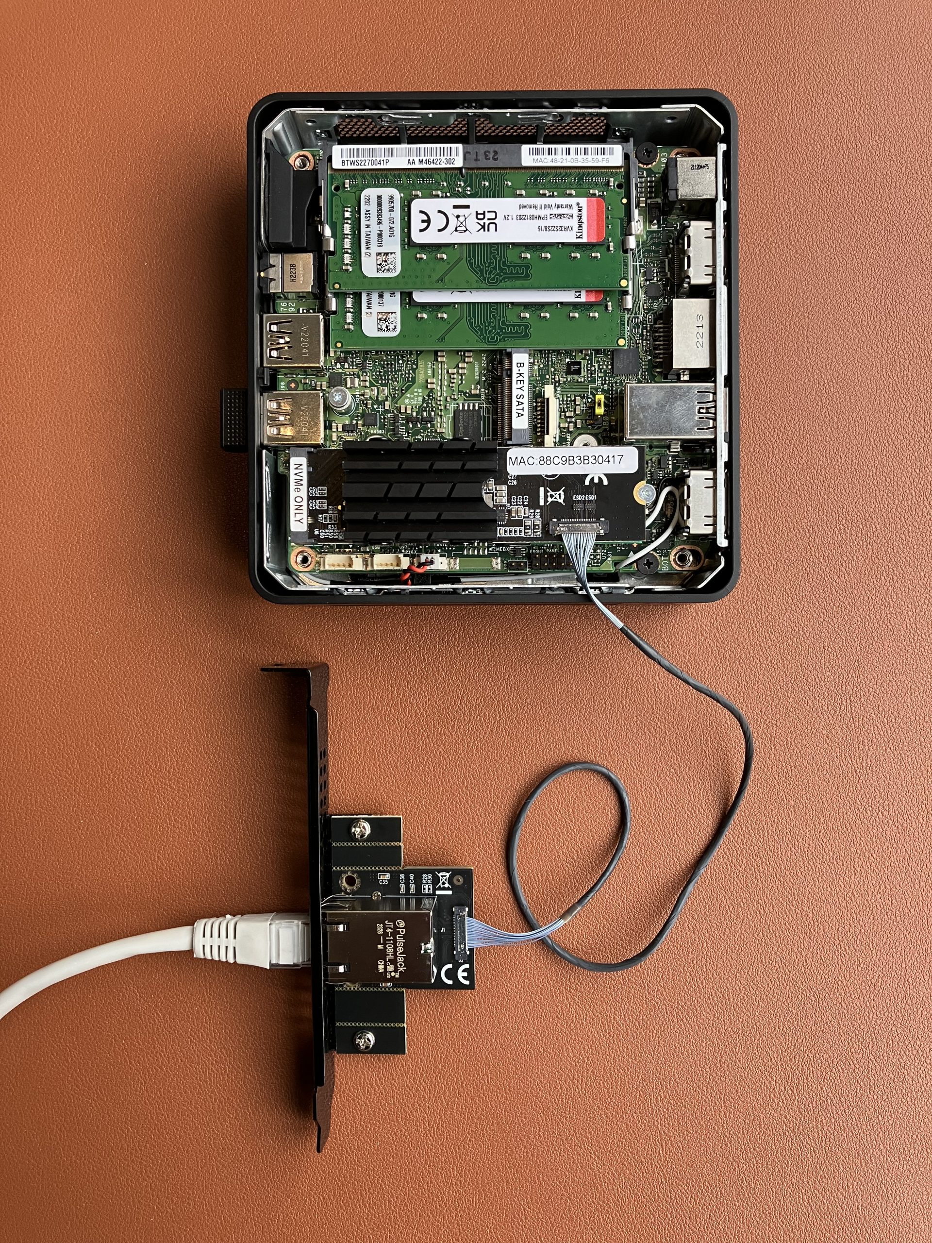
Remove NVMe from the M.2 slotInstall 10 GbE network adapter insteadIntel NUC with 10 GbE adapter connected to 10 GbE switch
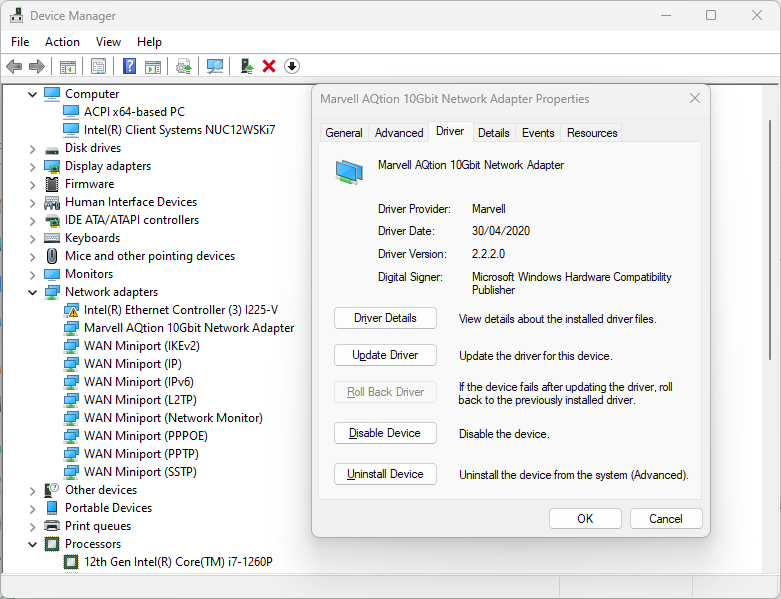
Install Windows 11 23H2 version on a USB SSD drive, boot Windows, run Windows Update, voila!
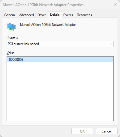
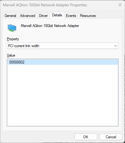
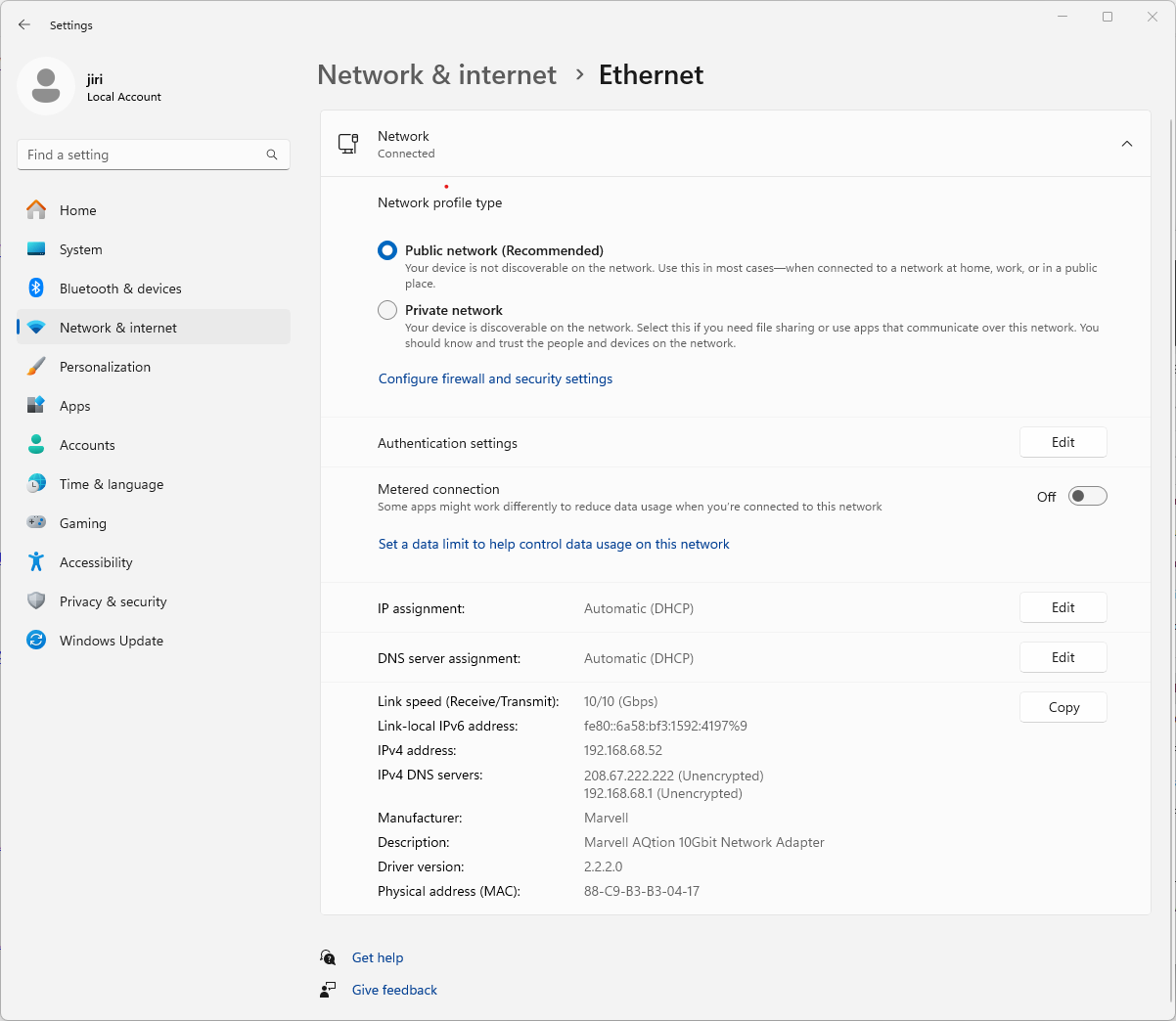
Windows Update installed latest driver automaticallyIt uses PCIe Gen 3And x2 link width10 Gbps Full Duplex
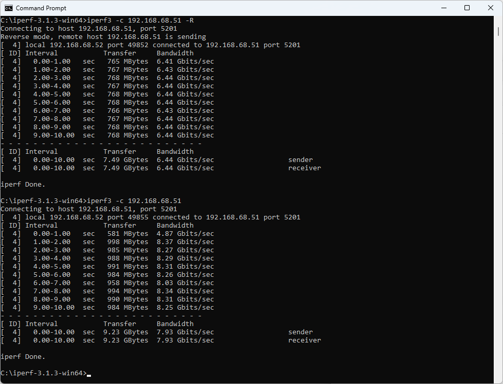
With default iperf3 settings we get 6.44 Gbps/7.93 Gbps in the downlink and uplink direction respectively. Not bad, but is that it? Of course not.
iperf3 with default settings
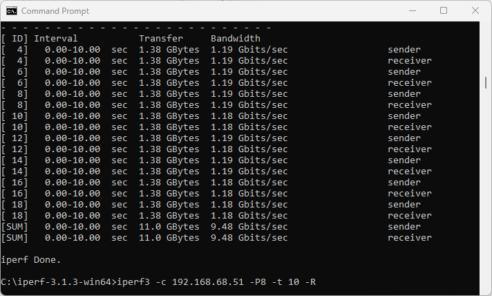
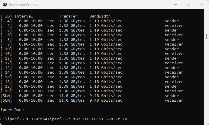
I don’t really want to enable Jumbo frames as it’s not always possible to enable Jumbo frame support end-to-end, especially if part of the network doesn’t support it or isn’t under your management. Fortunately, 8 parallel TCP streams in iperf3 do the trick for us. We get 9.48 Gbps download speed.
9.48 Gbps download
In the upstream direction from this NUC to my MacBook with 10 GbE adapter, we also get 9.48 Gbps. I am happy. You? 😉
9.48 Gbps upload
Summary
After all, this 10 GbE M.2 network adapter is indeed capable of pushing 9.48 Gbps of traffic in either direction. But! It is not really a good choice for a system like Intel NUC. I can’t pop the lid back on, the heatsink is too tall. Frankly, I can’t recommend this adapter at all. It runs hot at 84° Celsius in idle.
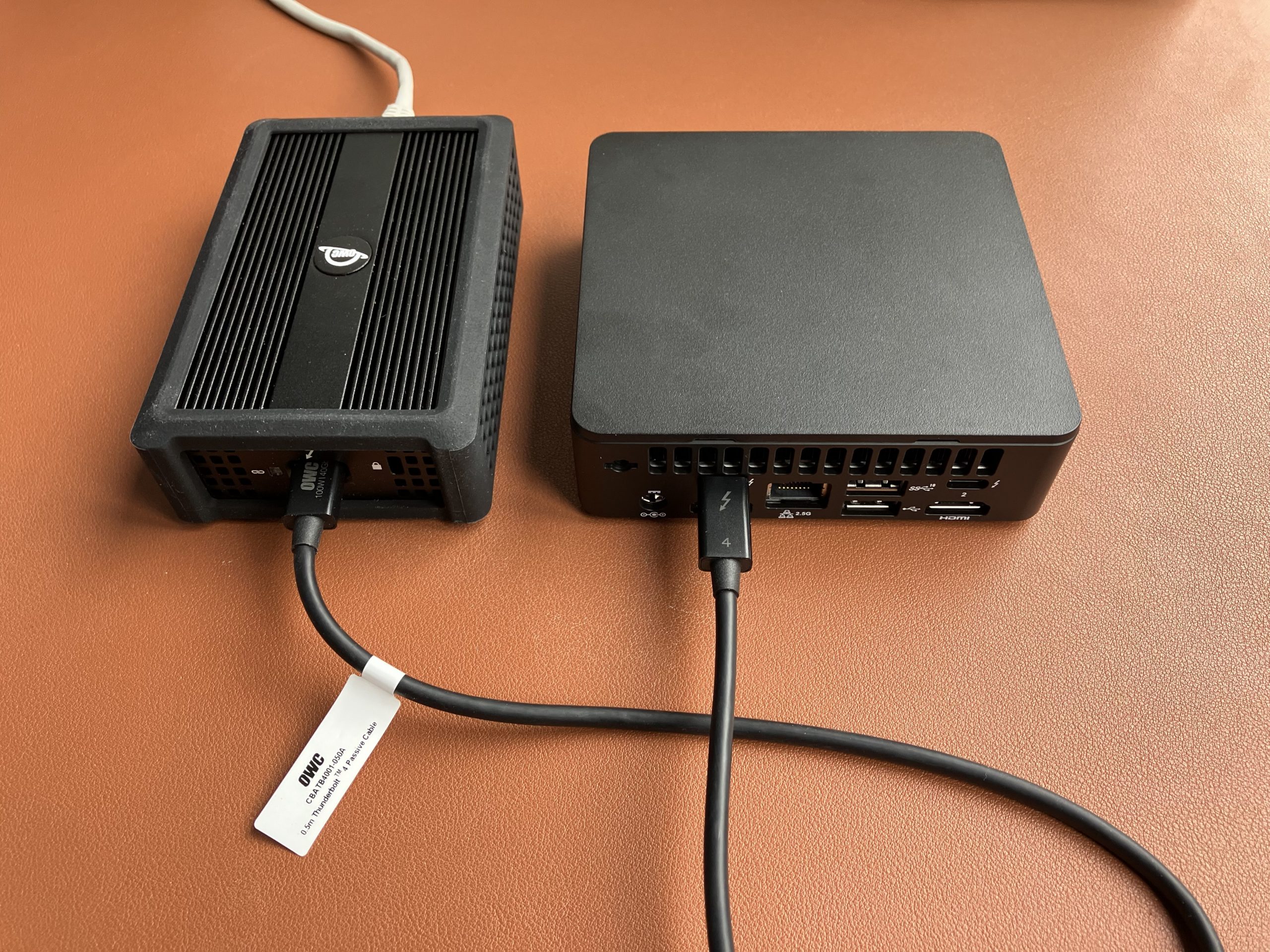
If you are looking for a daily driver, and your system supports Thunderbolt, get yourself this OWC 10GbE to Thunderbolt adapter. Here is my test. It works out of the box on Windows (I tested this Intel NUC 12th Gen) and macOS (I tested MacBook Pro M1 and M2). Interestingly, it uses the same chip as the above M.2 adapter. Just compare the two products and their heatsink sizes. The AQC107 keeps the main CPU utilisation very low, but it produces a significant amount of heat.
OWC 10 GbE to Thunderbolt network adapter connected to Intel NUCOWC 10 GbE to Thunderbolt network adapter connected to MacBook
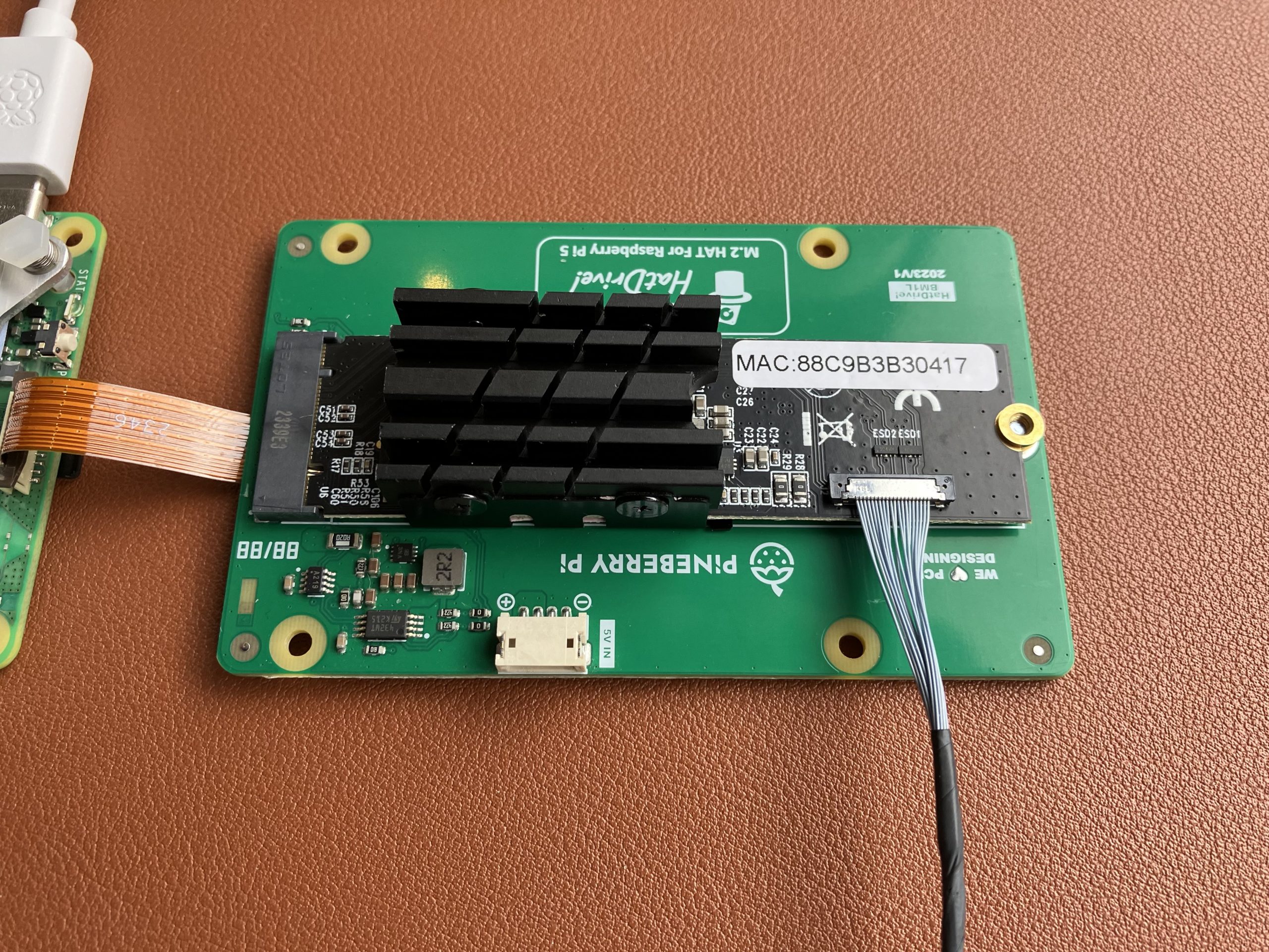
Raspberry Pi 5 comes with PCI Express connection and a number of HATs (hardware attached on top) and Bottoms (the opposite of that) are now available for sale. That unlocks some very exciting options. Let’s see how fast can a 10 Gigabit Ethernet adapter on Raspberry Pi 5 go, shall we?
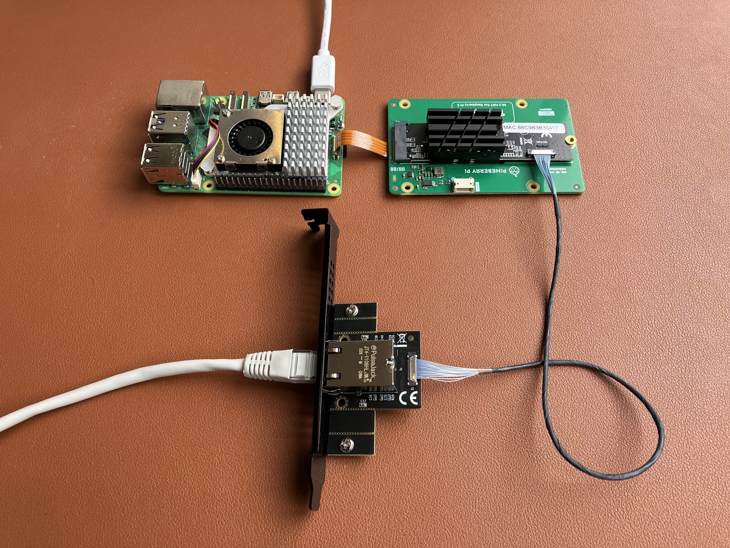
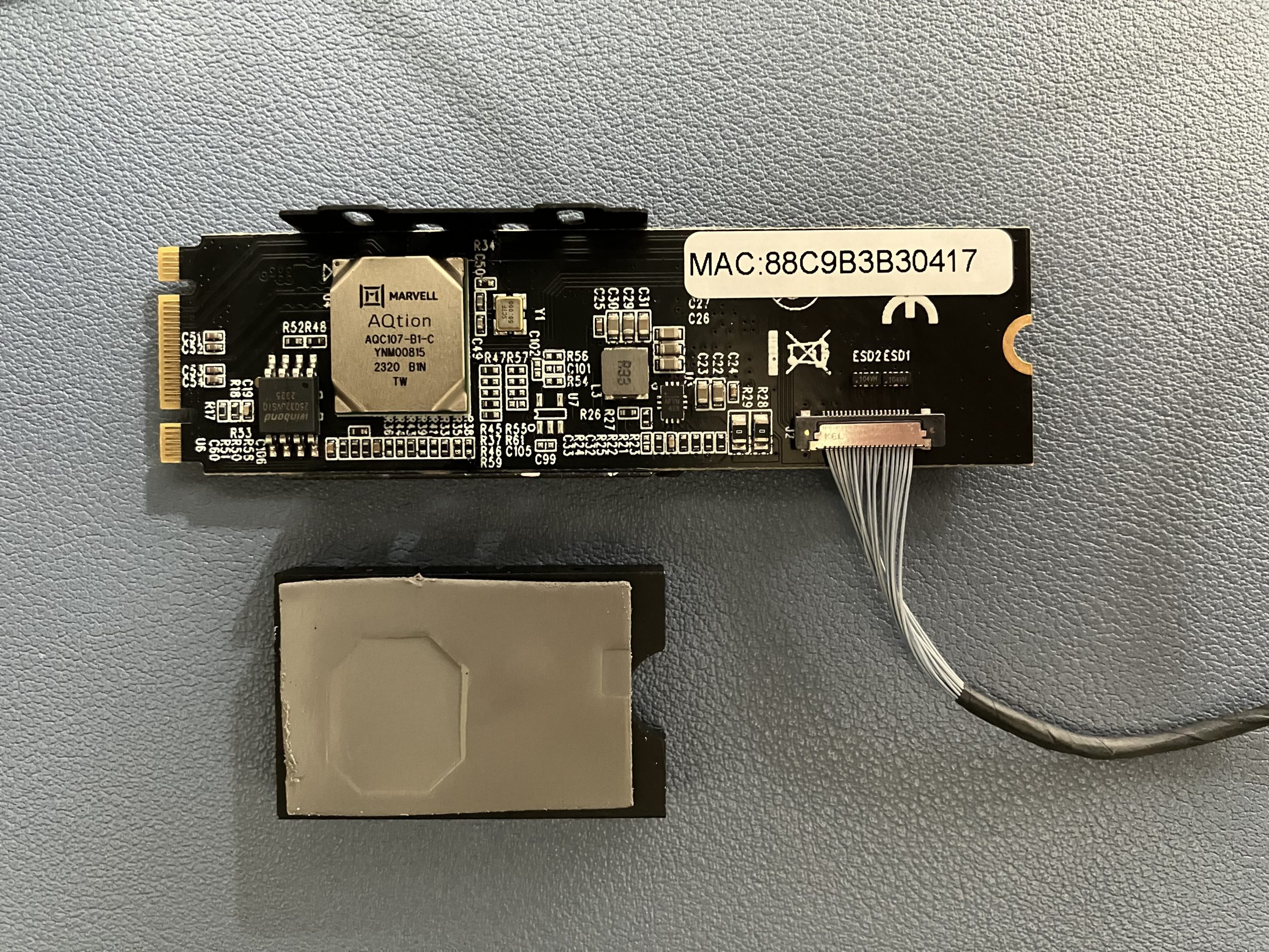
Pineberry’s HatDrive! Bottom proved to be really handy for converting Pi’s PCIe connection to M.2 M-key format. My Kalea-Informatique 10 Gigabit adapter uses exactly that, so that’s a match. Why did I choose this adapter? Very unscientifically this time – it was the first readily available and I was in a fail-fast mood :)
10 GbE adapter connected to Raspberry Pi 5Pineberry HatDrive! Bottom board with 10 GbE network adapterDetail of the AQC107 chip powering the network adapter
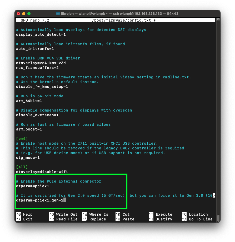
Enable PCIe port on Raspberry Pi 5
First things first. We need to enable the PCIe connector on the Pi.
sudo nano /boot/firmware/config.txt

# Enable the port
dtparam=pciex1

# Configure PCIe Gen
dtparam=pciex1_gen=2
Enable PCIe and configure mode
Build custom Linux kernel and include the Aquantia driver module
Vanilla Raspberry Pi OS doesn’t include the Aquantia AQC107 kernel module. So we need to burn a micro SD card with a vanilla Raspberry Pi OS Bookworm image, boot the Pi 5 and build a customised kernel.
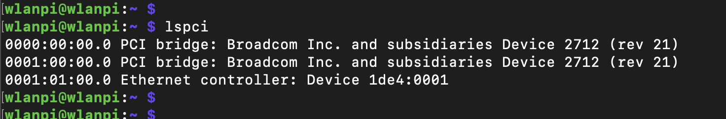
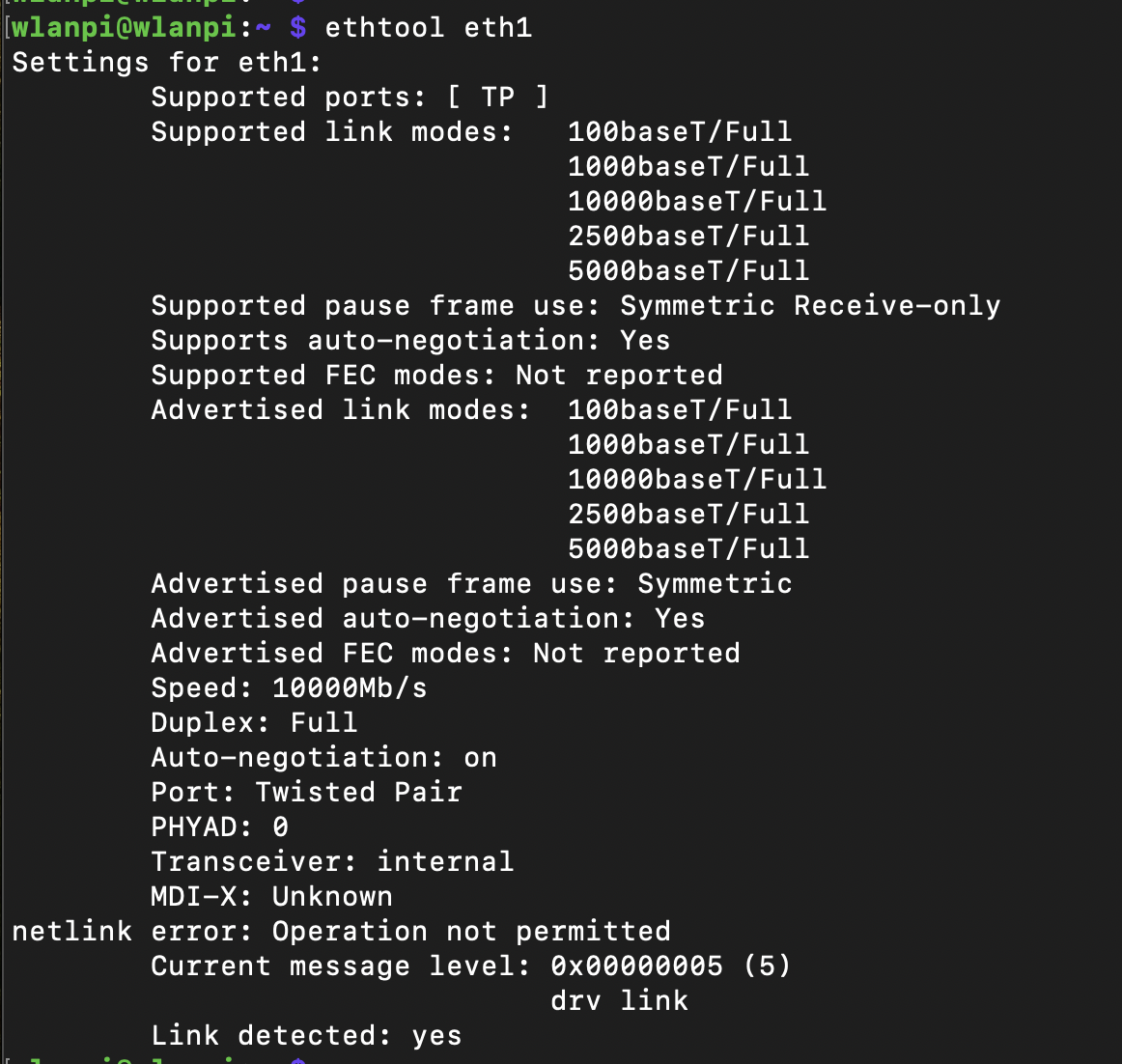
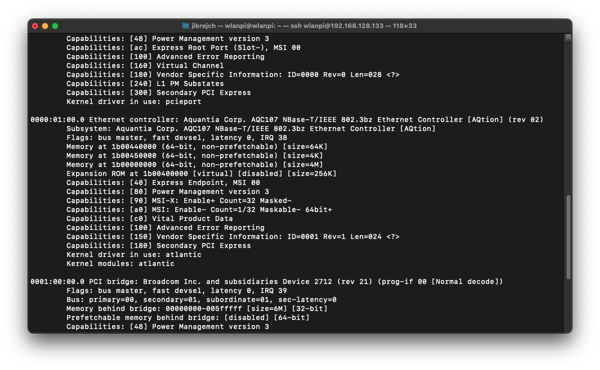
After reboot, the LED light on the network adapter should come to life and we can capture first impressions.
Adapter recognised10 Gbps Full Duplexlspci -v output
Temperature
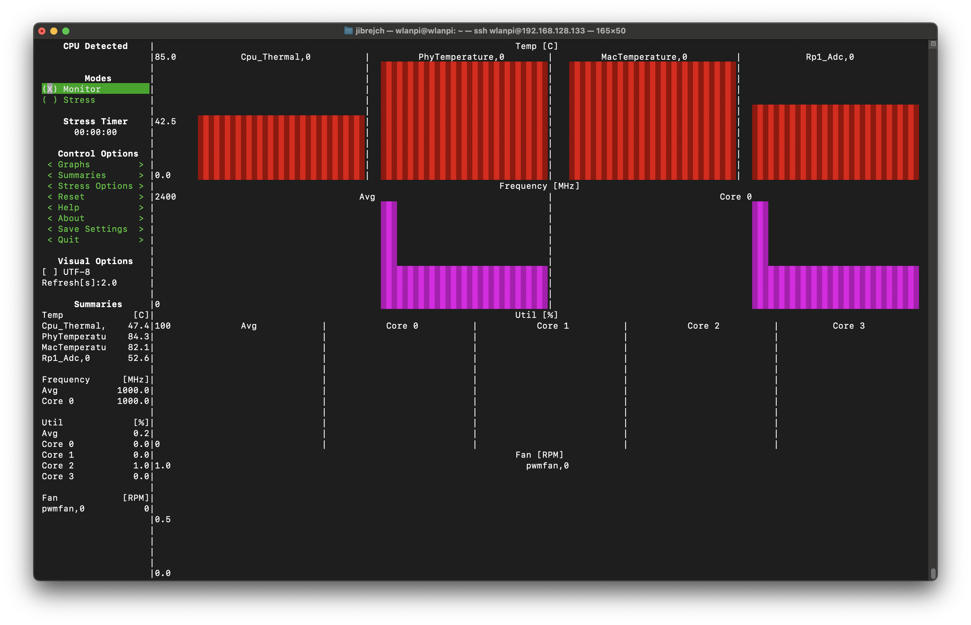
First thing you will likely notice is how hot this network adapter runs. It runs at 85° Celsius in idle which is slightly worrying and you can literally burn your fingers if you are not careful. Thumbs down on the thermal design front.
High idle temperature
Under load, surprisingly, it ‘only’ runs 0.5° warmer.
High temperature under load
How fast can it go then?
Raspberry Pi 5 officially supports PCIe Gen 1 and Gen 2. It is not certified for Gen 3.
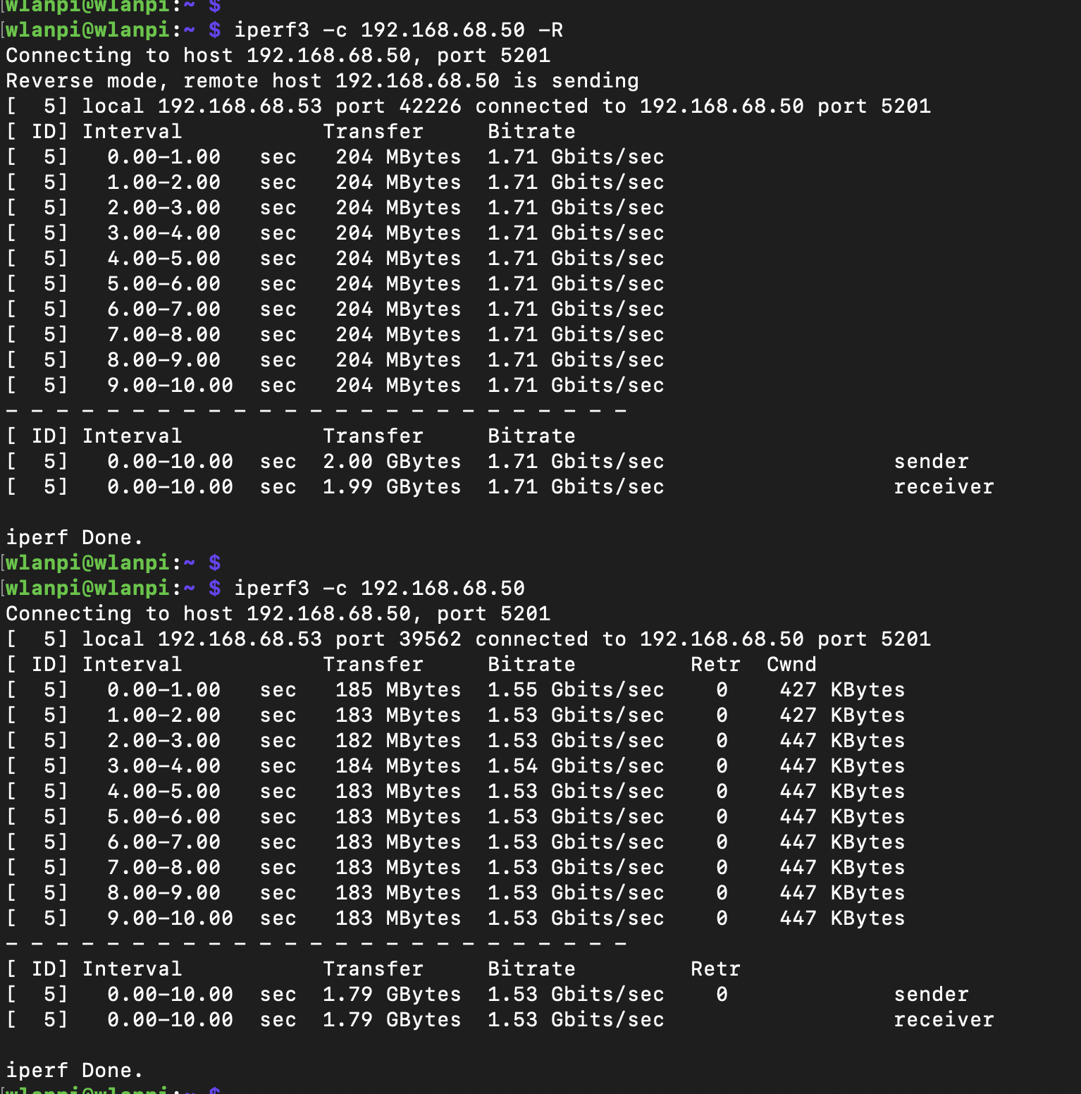
PCIe Gen 1 mode
In this slowest mode, I got 1.71 Gbps/1.53 Gbps iperf3 TCP results with standard iperf3 settings. No jumbo frames, no other tweaks.
PCIe Gen 1 throughput
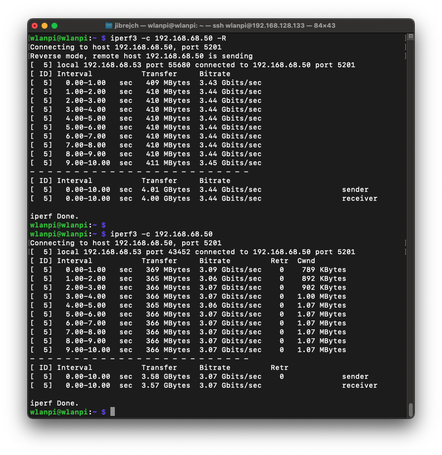
PCIe Gen 2 mode
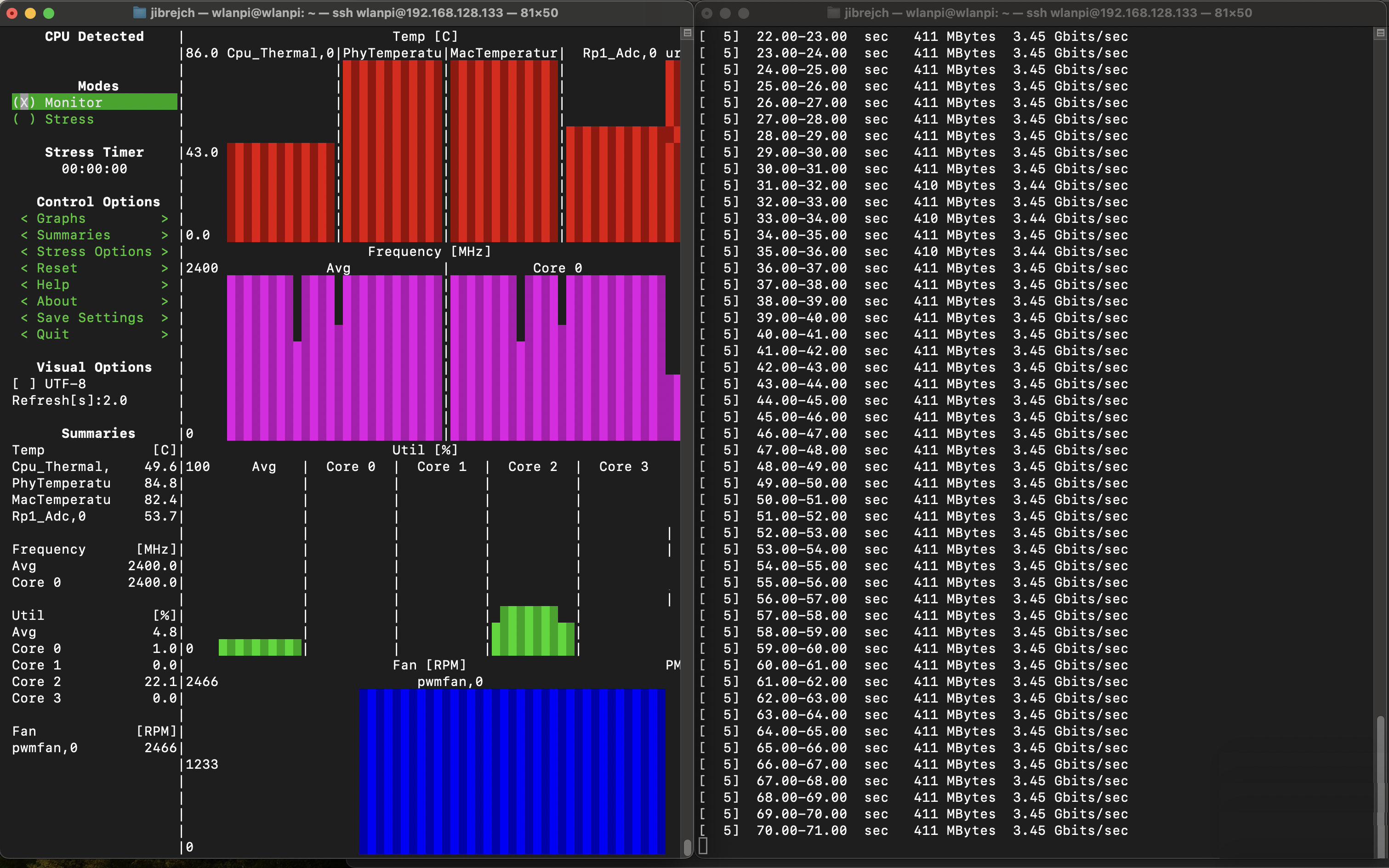
Again, with standard iperf3 settings, I measured 3.44 Gbps/3.04 Gbps TCP throughput between 2 computers both connected to 10 Gbps switch ports via 10 GbE Full Duplex.
PCIe Gen 2 throughput
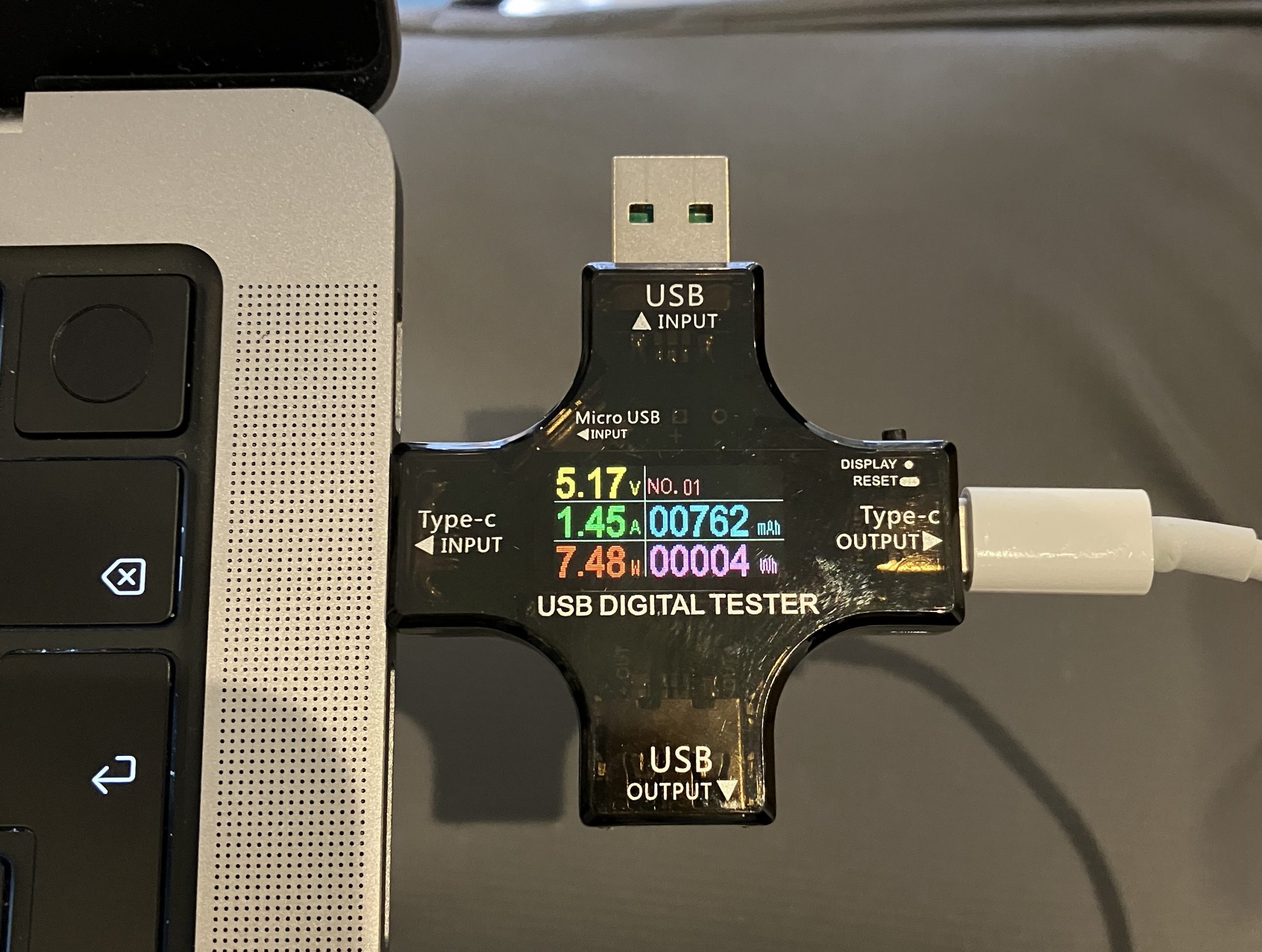
In idle conditions, this setup draws 7.5 W, and 8.9 W under 10GbE adapter iperf3 -R load (3.45 Gbps). Using more iperf3 parallel streams (the -P parameter) did not help at all.
Power draw
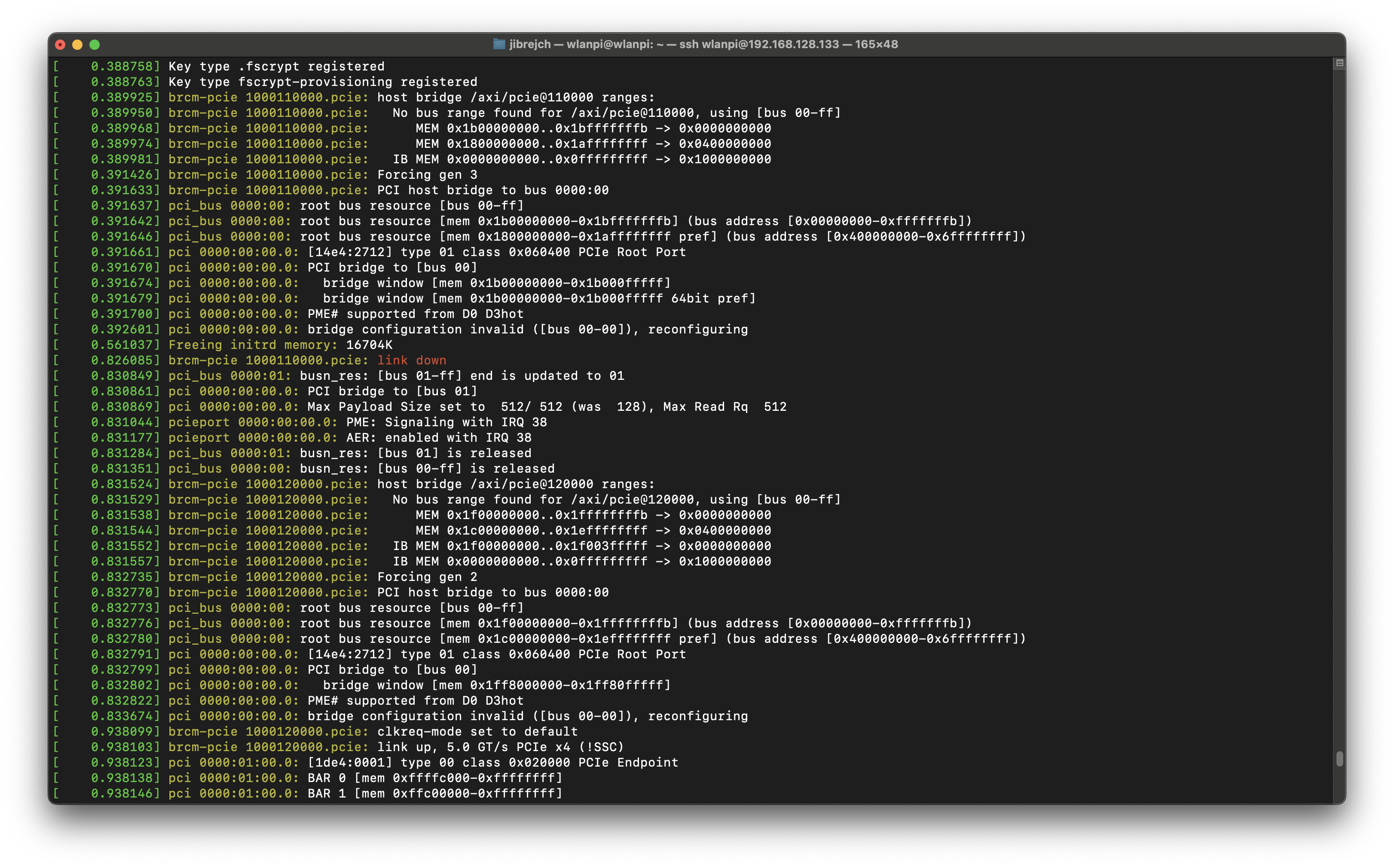
PCIe Gen 3 mode
The adapter supports PCIe Gen 3, but it doesn’t work with the Pi. The Pi is not certified for Gen 3, so I can’t say anything bad about this. The Ethernet adapter is not recognised in Gen 3 mode, and no interface is present in ip a. Sometimes the Pi will fail to boot.
According to dmesg, the Pi forced Gen 2 mode:
brcm-pcie 1000110000.pcie: link down
brcm-pcie 1000120000.pcie: Forcing gen 2
Forcing PCIe Gen 2 mode athough Gen 3 has been configured
I powered my Pi from M2 MacBook USB-C port. So I thought, I might be running into under-voltage issues. I tested the official Raspberry Pi 27 W (5 V * 5 A) AC power and it made no difference.
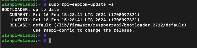
Did you upgrade Raspberry Pi 5 firmware?
Yes, I did. It is running the latest version available as of March 2024.
Latest firmware installed
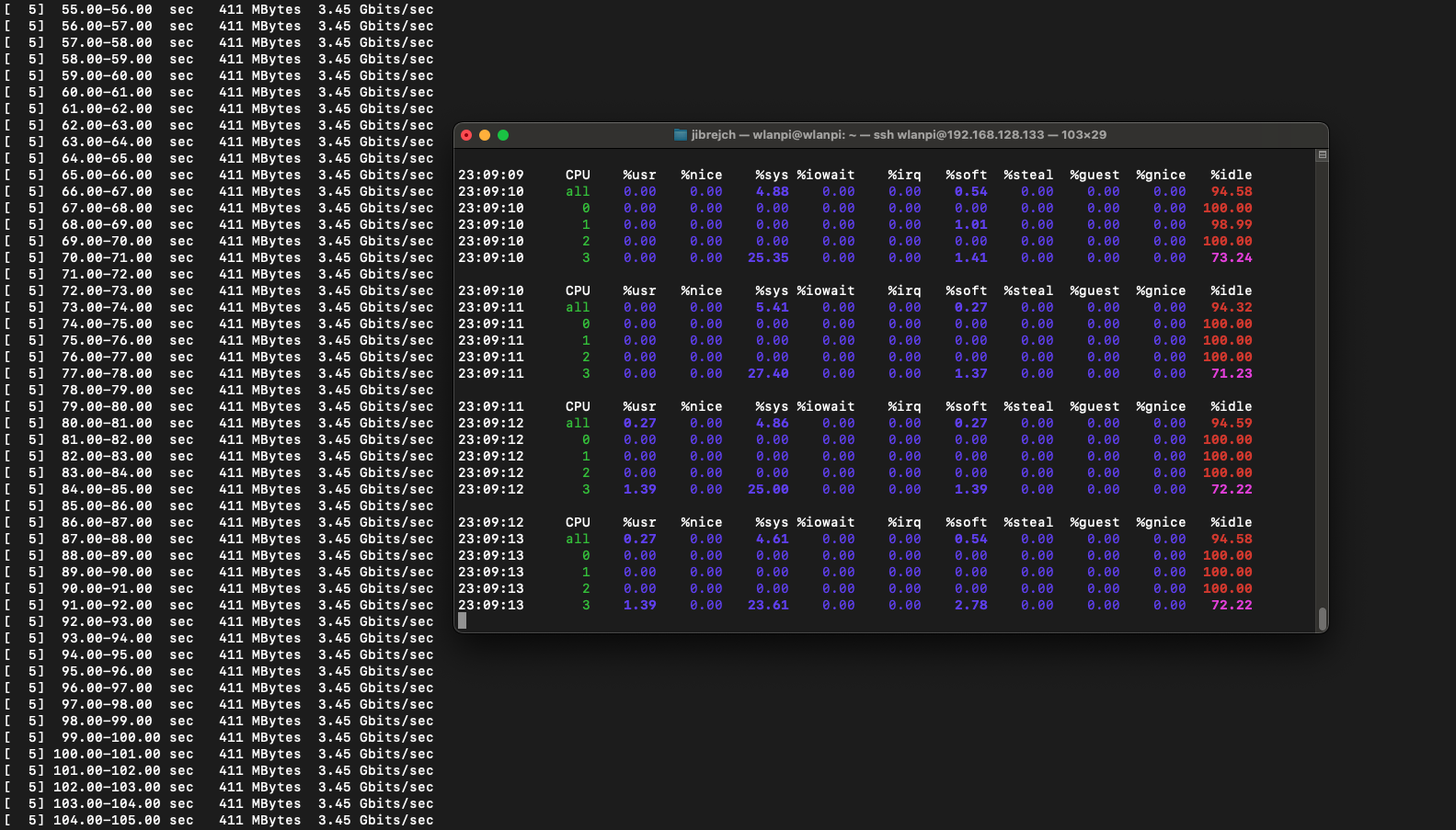
Low CPU utilisation
One feature I really enjoyed is the extremely low CPU utilisation under load. I saw slower 2.5 GbE adapters hammer CPU with interrupts, but that’s not the case for this NIC. AQC107 does really good job at keeping the CPU cool.
Low Raspberry Pi 5 CPU load under network load
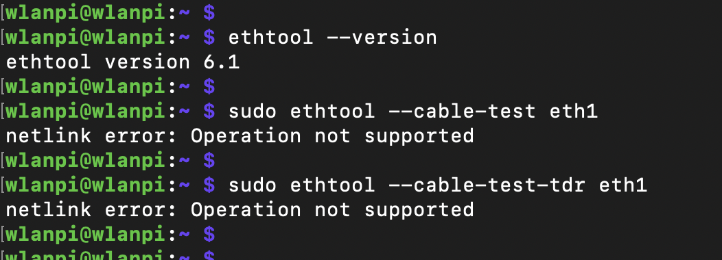
Cable analytics
Marvell supports Cable Diagnostics feature which uses TDR to measure cable length and detect Ethernet cable for defects. Unfortunately, it doesn’t seem to be supported on the AQC107 chip.
Cable Diagnostics not supported
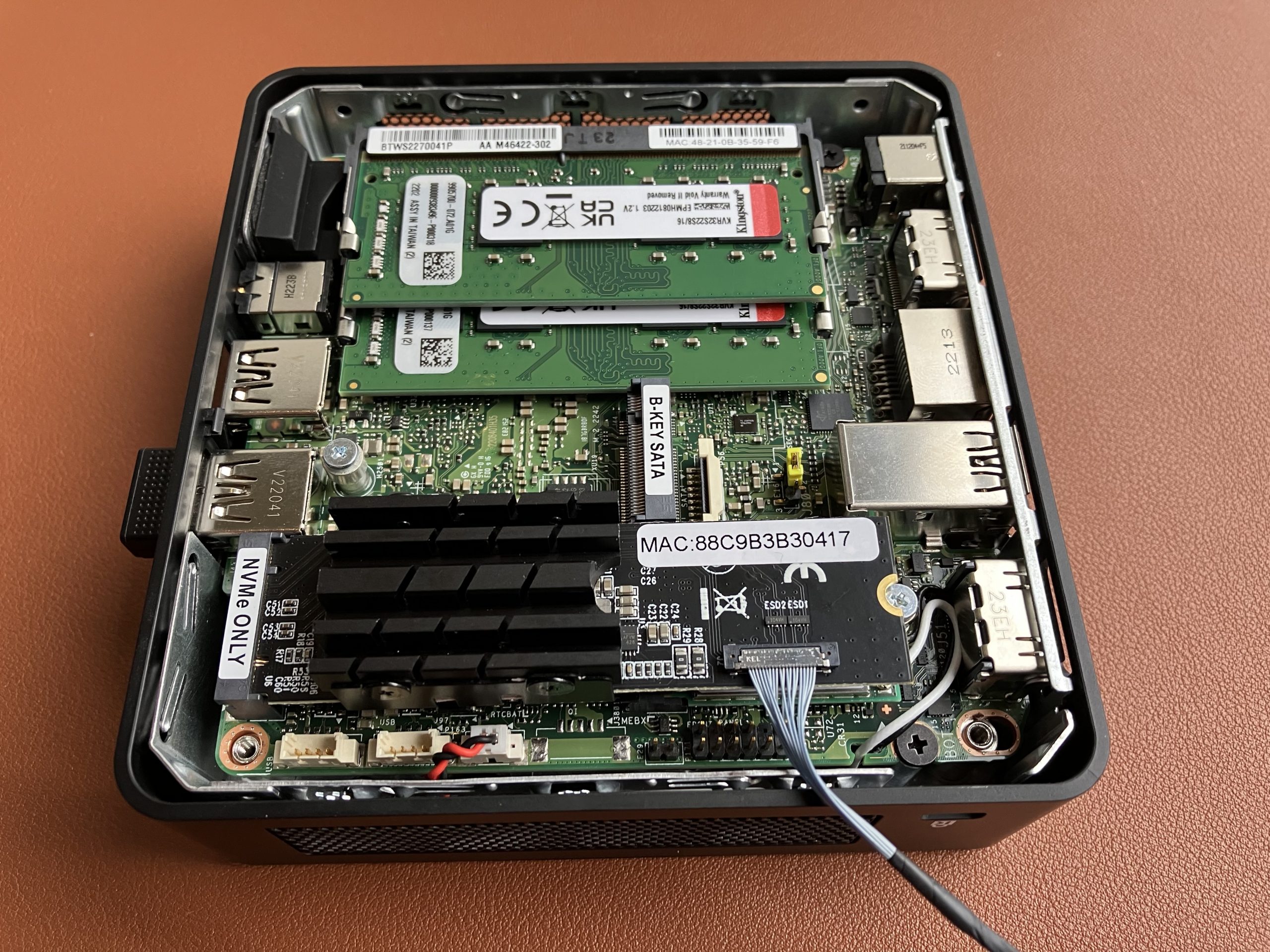
Can you get 10 Gbps out of this adapter at all?
I am glad you asked. How does an Intel NUC with this 10 GbE adapter sound? I’ve just tested it, here you go.
Intel NUC with 10 GbE adapter
Summary
The high operating temperature really makes this adapter something I can’t recommend. With maximum throughput below 3.5 Gbps, I think you would be better off choosing a 2.5 Gigabit Ethernet adapter, which runs cool and delivers 2.35 Gbps/2.35 Gbps throughput.
Have you tested any other 10 GbE adapter? Did you get better results? Did you find any 2.5 Gbps Ethernet adapter that supports Cable Diagnostics? I am all ears.
What is a ‘key’? It is formed of the notch on the Wi-Fi adapter PCB, and plastic blob separating pins inside the M.2 slot. The idea is to prevent users from plugging incompatible cards to the slot, and avoid any ‘magic smoke events’. Here is more about M.2 and the individual key types if you are interested.
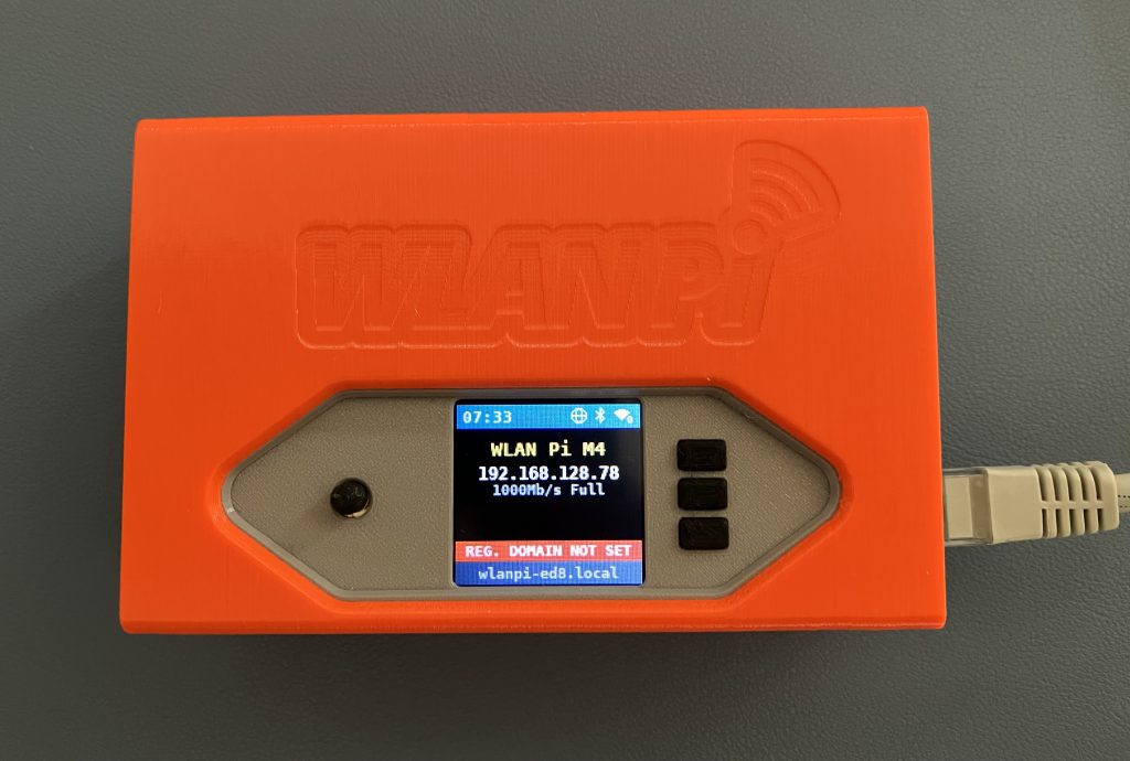
WLAN Pi upgrade kit
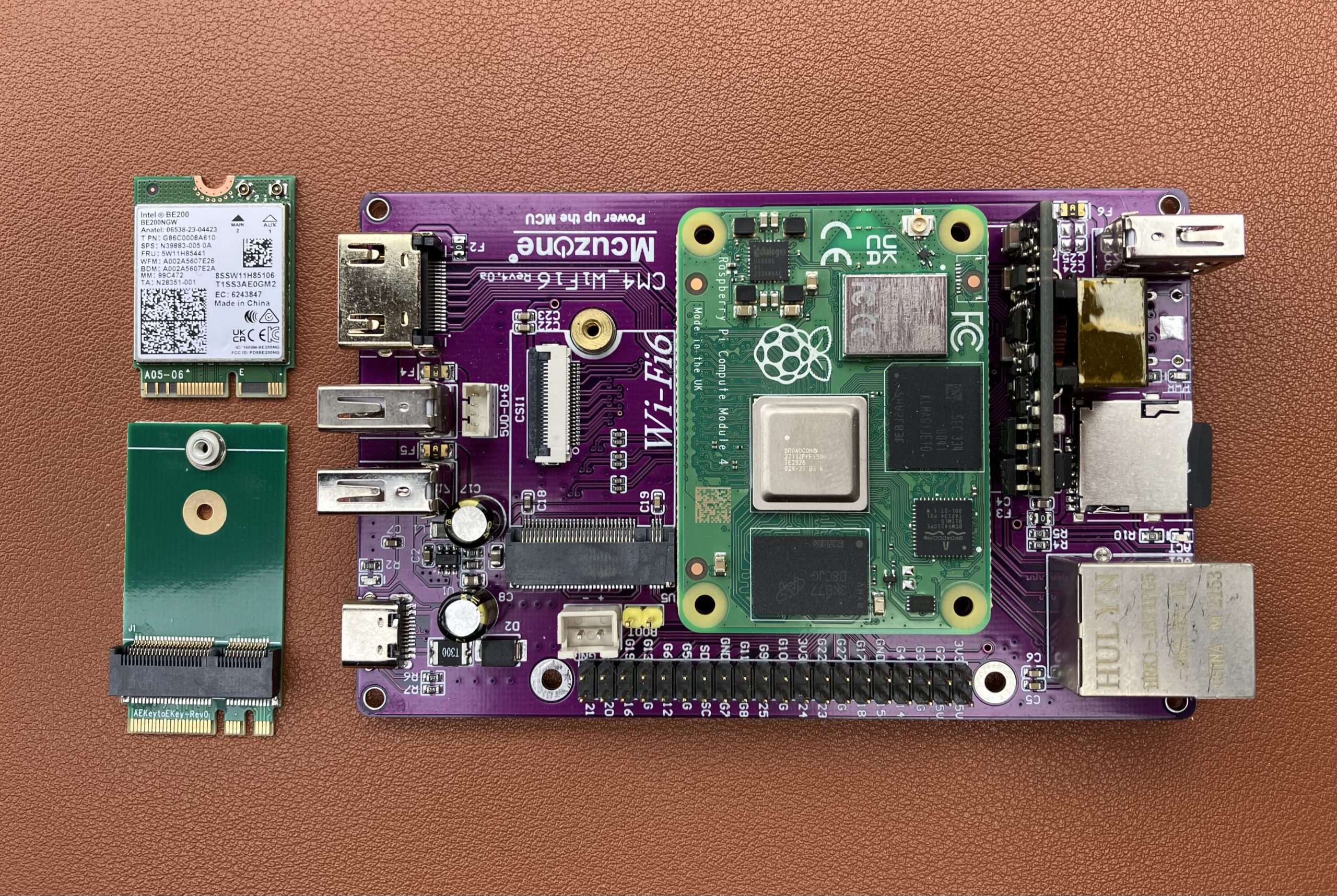
Since Intel adapters use E-key and WLAN Pi M4 uses A-key, we needed to build an adapter. Badger Wi-Fi has the upgrade kit in stock. It comprises of the Oscium M.2 A-key to E-key adapter, Intel BE200 Wi-Fi 7 adapter, and 2 little bolts to secure the adapter and the Wi-Fi module.
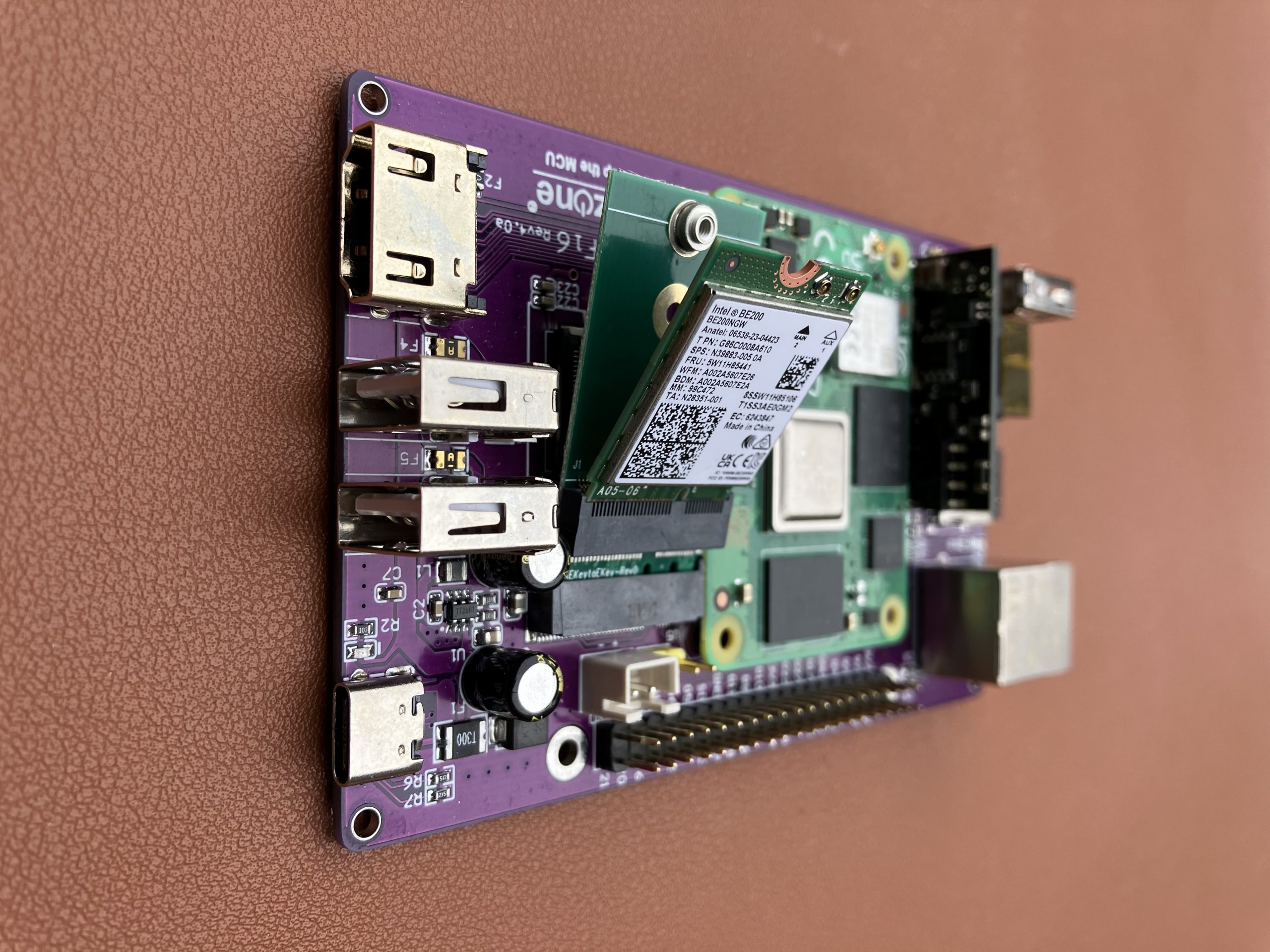
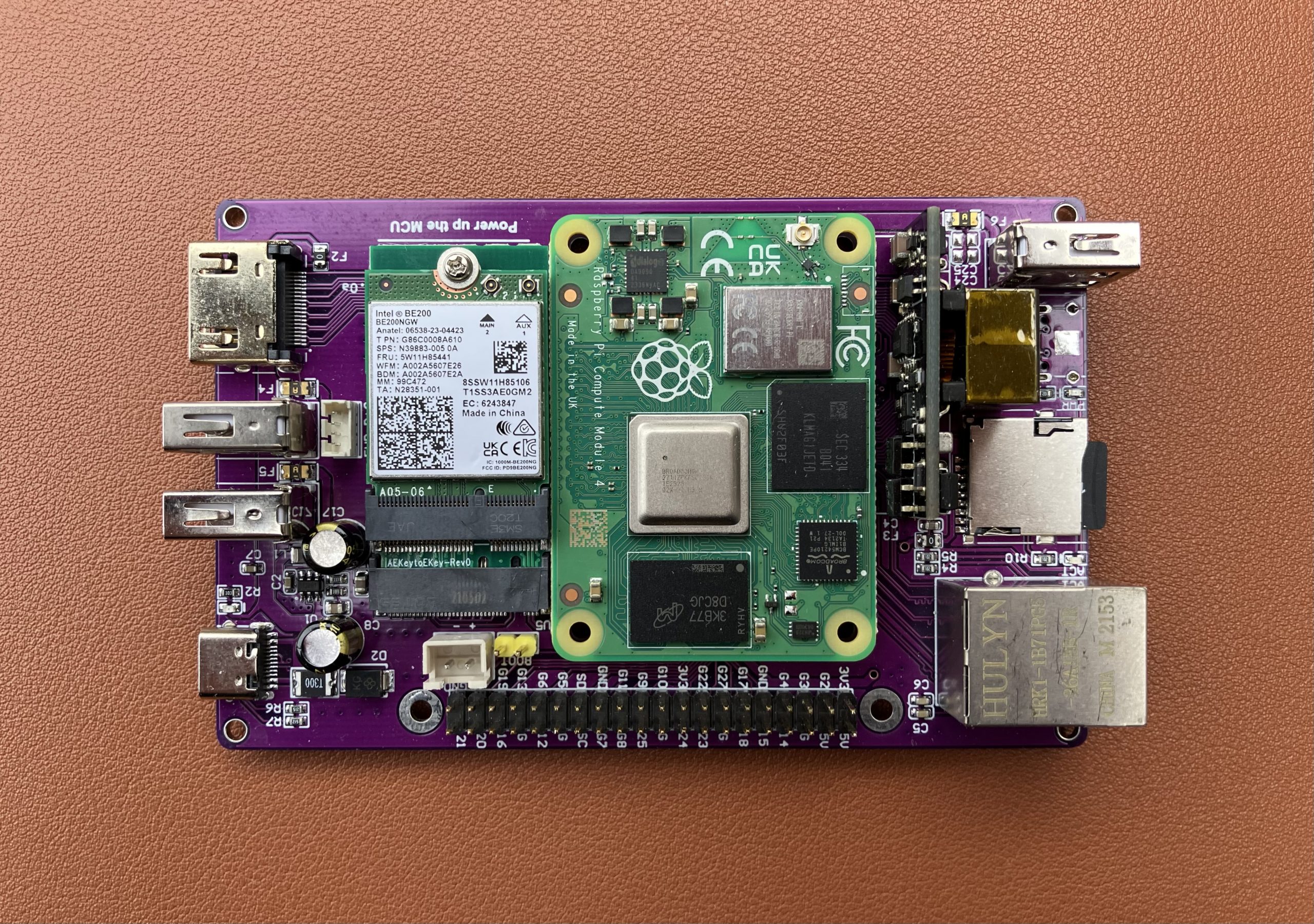
Here is how the ‘butterfly’ setup looks like. Intel BE200 sits onboard of the A-key to E-key adapter, installed in the M.2 slot.
We are ready to connect existing tri-band antennas, and assemble the unit.
Software support
Make sure to either upgrade Linux packages to their latest versions using sudo apt update && sudo apt upgrade command, or download and flash the latest WLAN Pi software image on your SD card. Release 3.2.0 supports Wi-Fi 7 Intel BE200 adapter out of the box with no effort whatsoever on your part.
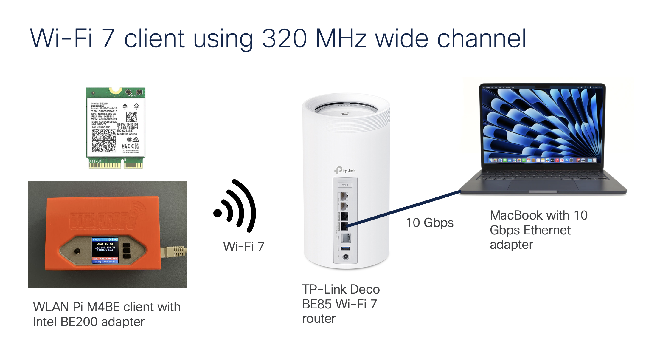
Wi-Fi 7 in action
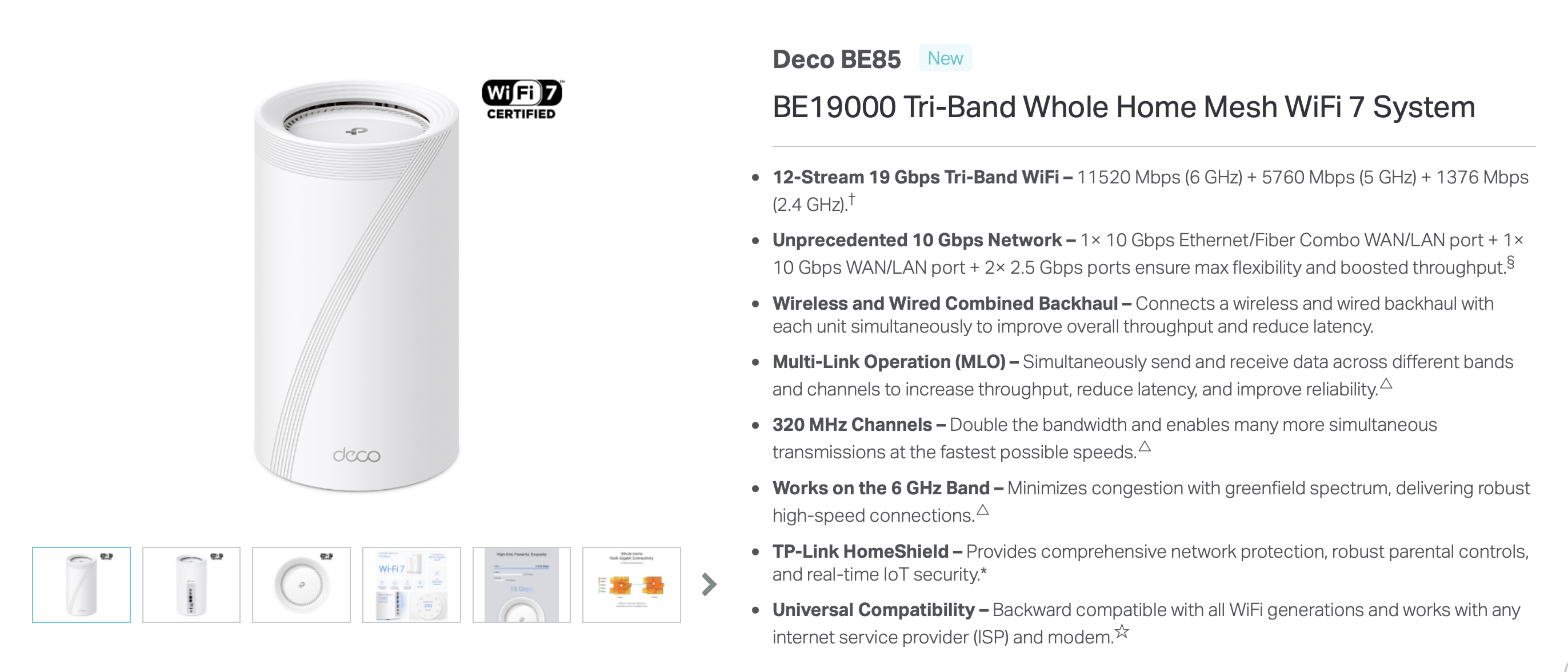
For this demonstration I use a consumer Wi-Fi 7 router TP-Link Deco BE85 BE19000. Simply because it is available, Wi-Fi 7 certified, and it supports 320 MHz channel width – not that one would deploy that in an enterprise environment, but mainly to test the maximum Wi-Fi throughput of the Pi.
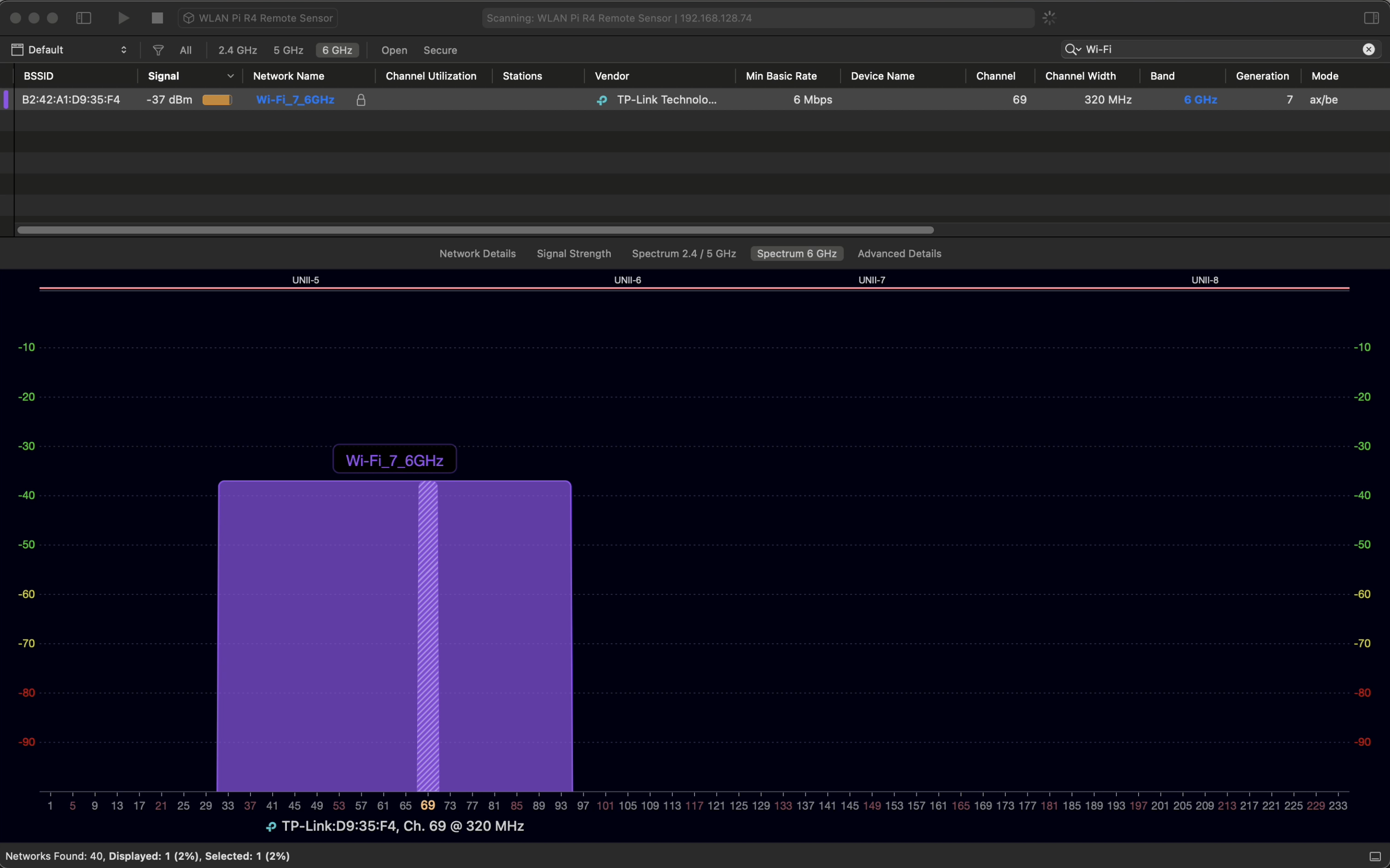
A bug in macOS doesn’t allow Macs to correctly recognise Wi-Fi 7 networks. Instead of Wi-Fi 7 320 MHz wide network, my MacBook reports Wi-Fi 6 and 160 MHz wide channel. So, we will use another WLAN Pi and its Wi-Fi radio as a Remote Sensor in WiFi Explorer Pro – you need the Pro version to do this.
Nice, Wi-Fi 7 AP!
Wi-Fi 7 network
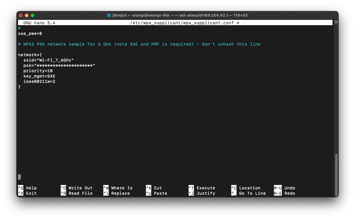
Connecting the WLAN Pi as a Wi-Fi 7 client only takes few lines of wpa_supplicant config.
sudo nano /etc/wpa_supplicant/wpa_supplicant.conf
Wi-Fi 7 network settings
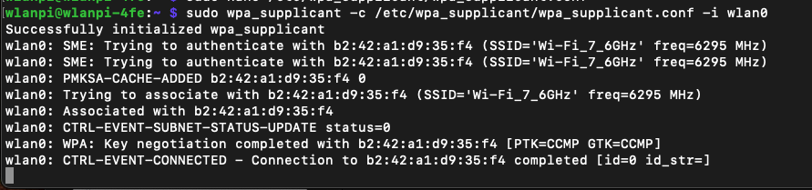
And we have successfully connected the WLAN Pi as a Wi-Fi 7 client to the AP using this command.
Run this command to make sure the WLAN Pi requests an IP address from DHCP server running on the router:
sudo dhclient -i wlan0 -v
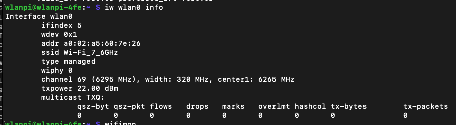
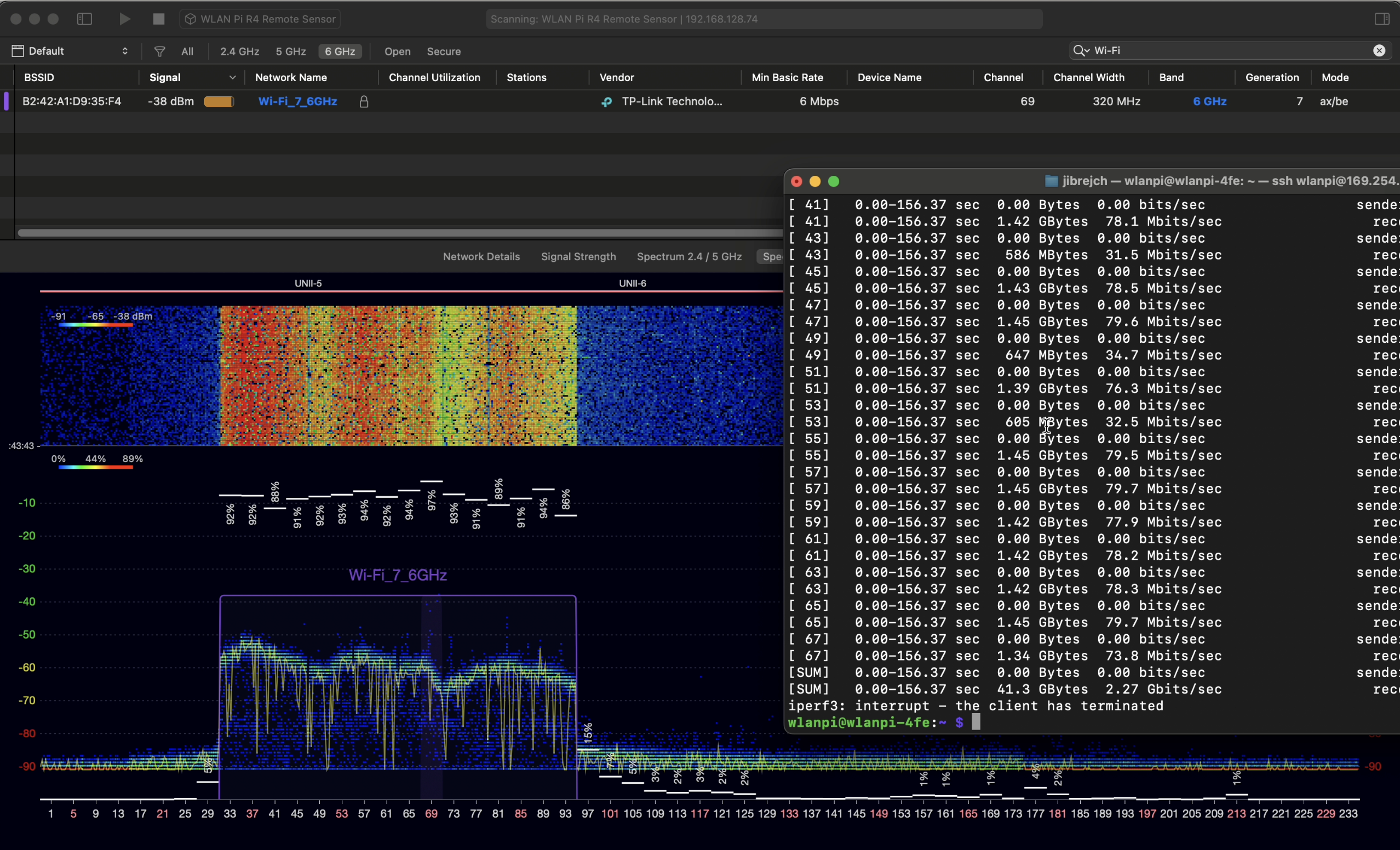
What channel are we using? 320 MHz channel width? Indeed.
Adapter and channel details
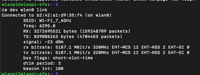
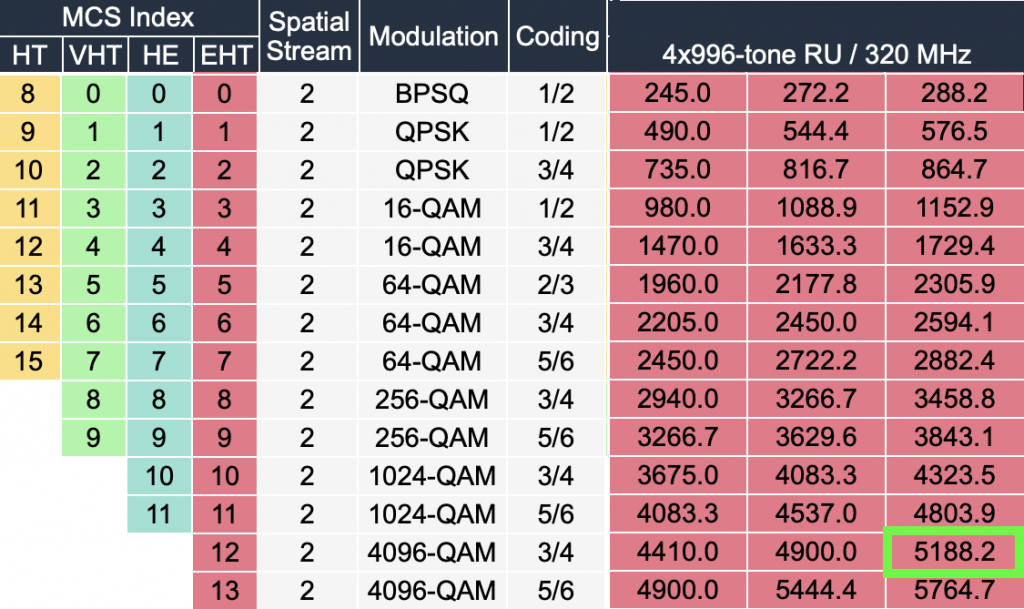
Before you ask, distance between the Pi and the router is sub 1 meter. What is the Wi-Fi data rate? We are using Wi-Fi 7 (EHT), 2 spatial streams, MCS 12 and 4096-QAM and short guard interval of 0.8 µs.
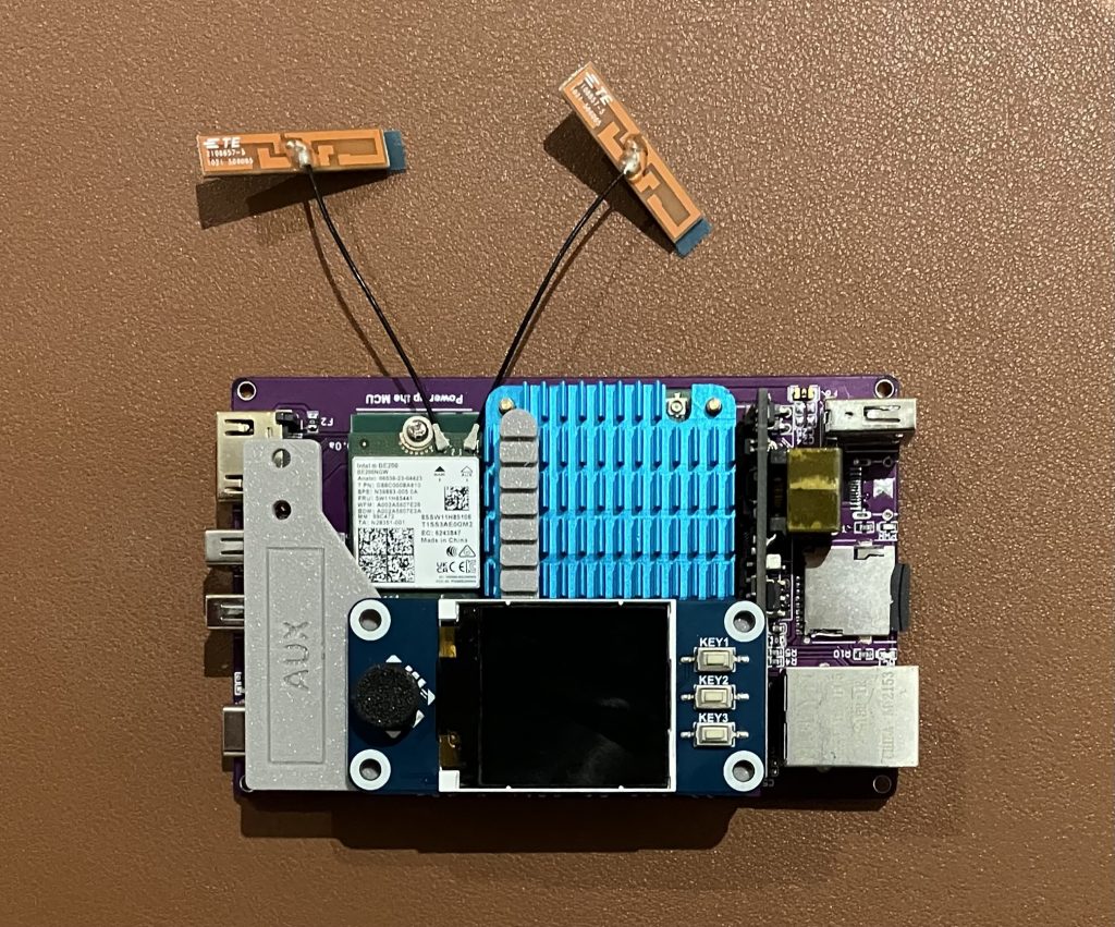
I hardly ever achieved MCS 13. To maintain MCS 12, I had to stay within about 1.5 meter distance from the router. I got best results with antennas position in this ‘V’ pattern.
V-shaped antenna placement
With a different client device designed for Wi-Fi 7 from the ground up (with professional quality antennas and placement), I would hope for slightly longer MCS 12 and MCS 13 range.
With the help of Oscium WiPry Clarity 6 GHz spectrum analyser connected to another WLAN Pi, we can monitor the life spectrum and see how much red the iperf3 test introduces. We are able to achieve download TCP speed of 2.27 Gbps and upload speed of 1.74 Gbps.
I used iperf3 -c 192.168.68.51 -P32 -R to test download speed, and iperf3 -c 192.168.68.51 -P32 for upload. Number of parallel streams set to 32 provided the best performance.
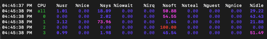
I was expecting 2.5 Gbps-ish throughput, which we have got quite close to. During the test, CPU of the WLAN Pi was running around 80 % utilisation, and interrupts were reaching 100 %. So, hardware of the WLAN Pi itself posed a bottleneck.
mpstat 1 300 -P ALL
High CPU utilisation due to interrupts
Orientation of the antennas mattered more than I expected to. Best position was a ‘V’ shape with antennas positioned away from the board. With AUX antenna placed 90 degrees relative to the Main antenna, data rates and throughput dropped. Perhaps there is RF noise from the board itself coming into play.
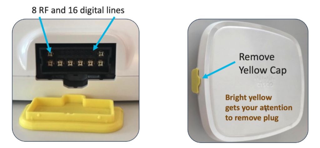
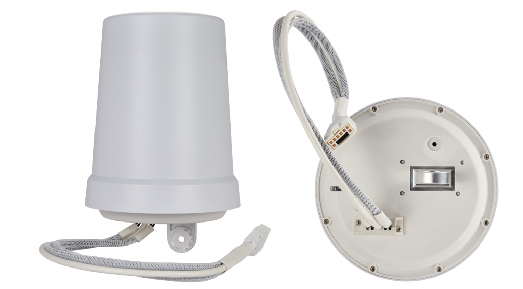
Cisco’s Catalyst 9130AXE access point (the external antenna model) doesn’t have any antennas built-in by design. It uses a DART connector with 8 RF lines and 16 digital lines. They carry the RF signals and allow communication between the AP and antenna.
All new C-ANT9101, C-ANT9102 and C-ANT9103 antennas connect natively using their directly-attached DART connector to the Catalyst 9130AXE access point. It significantly simplifies the deployment process, allows the AP to automatically detect the antenna model, type and gain, and it doesn’t allow any room for installation errors like loose RP-TNC connectors or swapped antenna RF ports.
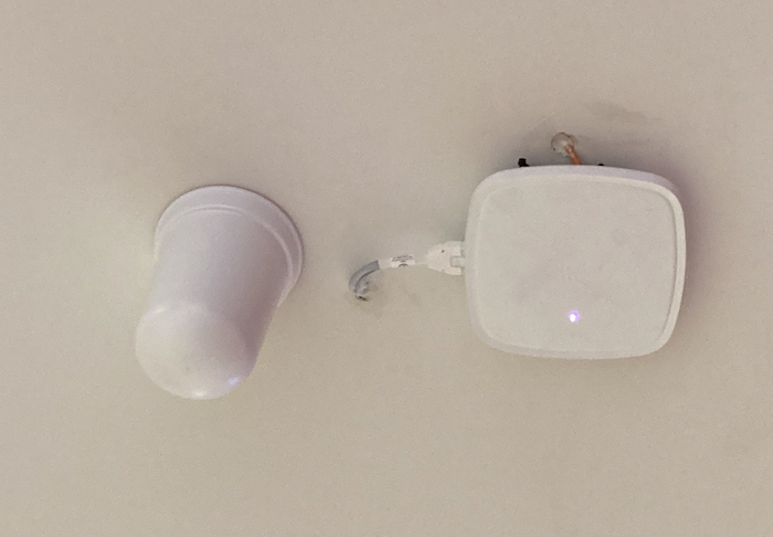
Here is an example of the new bell antenna C-ANT9102 with directly-attached DART connector.
And here is one connected to the C9130AXE-E access point.
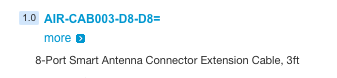
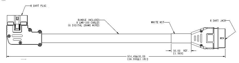
Now, if your scenario requires the antenna to be installed further away from the access point (inside of a freezer for example) there is a 3-feet DART extension cable for that sold by Cisco.
The part number is AIR-CAB003-D8-D8=.
It has 90-degree 8-port plug on one side and straight 8-port jack on the other.
Tentokrát jsem se pustil do otestování externího disku WD MyPassport Essential 500 GB. Zajímalo mě, jakým USB konektorem je osazený, jaká je reálná přenosová rychlost USB 3.0 a jestli jde použít i jiný kabel, než ten, který je součástí balení. Výsledek si můžete prohlédnout v tomto videu.
Závěry
Disk je předformátovaný systémem NTFS. Neobsahuje virtuální CD-ROM mechaniku se SmartWarem, což jistě oceníte. Nebylo to zrovna šťastné řešení.
Po připojení USB 3.0 kabelem do USB 3.0 portu počítače se rychlost čtení z disku pohybuje okolo 70 MB/s. Disk můžete spojit s PC také standardním MicroUSB kabelem. Potom nezávisle na tom, zda je váš počítač vybaven USB 3.0 portem či nikoliv, dosahuje rychlost přibližně 30 MB/s. Týž výsledků jsem dosáhl i reálným kopírováním velkého souboru ve Windows, takže nejde jen o teoretická čísla.
Pokud to jen trošku jde, používejte USB 3.0 port počítače a dodávaný kabel. Tím z disku dostanete maximum. V případě, že tento kabel zrovna nemáte při ruce, poslouží vám za cenu nižší rychlosti (USB 2.0) i obyčejný MicroUSB kabel.
Pokud jste někdy instalovali Windows, víte, že po prvním startu čistého systému je důležité zkontrolovat nerozpoznaná zařízení. Pro ta musíte sehnat ovladače a dodat je systému. Takových zařízení může být více. Jak ale zjistit modelové označení a rozlišit od sebe nicneříkající “PCI device” zařízení?
Instalace Windows někdy proběhne bez sebemenšího zásahu uživatele. V ideálním případě systém dokonce rozpozná veškeré hardwarové vybavení počítače, nainstaluje příslušné ovladače a vše proběhne v plném komfortu. S každou novou verzí se operační systémy blíží tomuto učebnicovému stavu. Na druhou stranu roste i počet nových zařízení, a tak je dosažení tohoto cíle během na dlouhou trať.
V případě staršího operačního systému, jakým jsou například Windows XP v kombinaci se specializovaným a málo rozšířeným hardwarem, není v silách automatického detekčního mechanizmu zařízení správně rozpoznat a nainstalovat odpovídající ovladač.
Podívejme se na malou ukázku. Na obrázku níže vidíte stav, v jakém se ocitla Windows XP bezprostředně po instalaci na testovaný počítač. Pohledem do Správce zařízení zjistíte, že systém naštěstí správně rozpoznal alespoň typy zařízení, takže pokud máte po ruce vhodné ovladače, stačí je nainstalovat. To provedete klepnutím pravým tlačítkem na vybrané zařízení a zvolením funkce Aktualizovat ovladač.
Pokud nemáte k dispozici konkrétní ovladač, je třeba nejprve přesně zjistit modelové označení zařízení, které se skrývá v útrobách vašeho stroje. Právě tento krok je zpravidla problém, se kterým se těžko vypořádává. Výrobci počítačů totiž sice poskytnou ovladače ke stažení na svých webových stránkách, ale modelová řada daného počítače je obvykle konfigurovatelná. Tím pádem se musíte dopídit toho, zda váš stroj obsahuje bezdrátový výrobce Intelu, DELLu, či zda je osazen adaptér jiného dodavatele. S identifikováním výrobce a modelu dané komponenty vám pomůže šikovný nástroj Unknown devices. Jeho výstupem je přesná informace, kterou potřebujete pro stažení správného ovladače.
V případě ethernetového síťového adaptéru nám Správce zařízení sdělil, že se jedná o “Síťový adaptér Ethernet”. Nástroj Unknown devices naproti tomu mluví zcela jasně a prozrazuje, že se jedná o zařízení výrobce Broadcom s modelovým označením BCM5750A1. S touto informací navštivte web výrobce dané komponenty či výrobce celého stroje a podle modelového označení stáhněte ovladač pro patřičnou bitovou a případně jazykovou verzi operačního systému.
Tip: Kromě těchto funkcí, můžete navíc v sekci Computer info – Product key najít produktové číslo, se kterým byla nainstalována vaše Windows.
Na serveru Síťařina.cz právě vyšel článek a především video s praktickou ukázkou možností zařízení MSNswitch. Díky němu můžete na dálku spínat elektrické zásuvky přes lokální síť i internet. Mě osobně se tato krabička velmi zalíbila, a tak ji mohu doporučit i vám.
Nedávno jsem tu měl kamarádův stroj nešťastně zalitý červeným vínem. Bezprostředně po incidentu duchapřítomně vyndal z notebooku akumulátor a snažil se klávesnici zvenčí vysušit. Když se mi pak notebook dostal do rukou, rozebral jsem ho a kompletně vyčistil. Naštěstí se víno nedostalo až na základní desku, takže se nejhorší obavy nenaplnily.
Po vložení akumulátoru na své místo a prvním spuštění ale nefungovala většina kláves. Pokud se ocitnete ve stejné situaci, v naprosté většině případů stačí objednat novou klávesnici a vyměnit ji. Samozřejmě je tu také možnost nechat všechnu práci na servisu, pokud se na výměnu svépomocí necítíte nebo nedisponujete odpovídajícím nářadím.
Po vylití vašeho oblíbeného nápoje do notebooku, na němž následně nefungují některé klávesy, tedy zpravidla stačí vyměnit klávesnici.