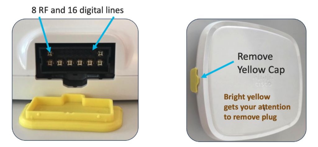
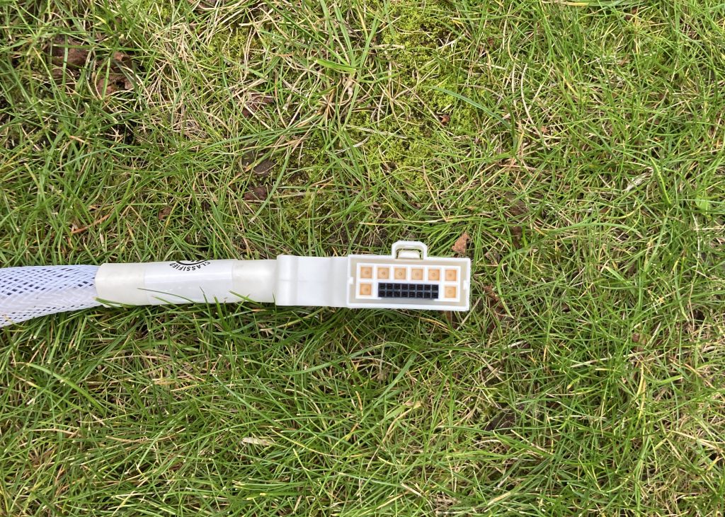
Cisco’s Catalyst 9130AXE access point (the external antenna model) doesn’t have any antennas built-in by design. It uses a DART connector with 8 RF lines and 16 digital lines. They carry the RF signals and allow communication between the AP and antenna.
All new C-ANT9101, C-ANT9102 and C-ANT9103 antennas connect natively using their directly-attached DART connector to the Catalyst 9130AXE access point. It significantly simplifies the deployment process, allows the AP to automatically detect the antenna model, type and gain, and it doesn’t allow any room for installation errors like loose RP-TNC connectors or swapped antenna RF ports.
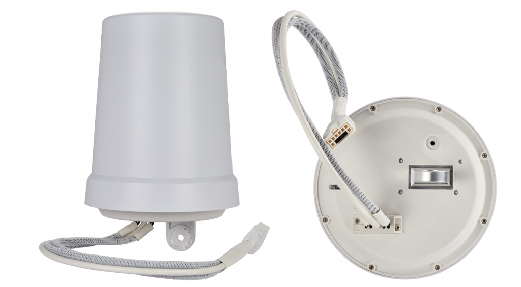
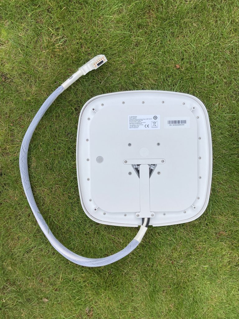
Here is an example of the new bell antenna C-ANT9102 with directly-attached DART connector.
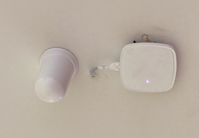
And here is one connected to the C9130AXE-E access point.
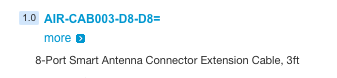
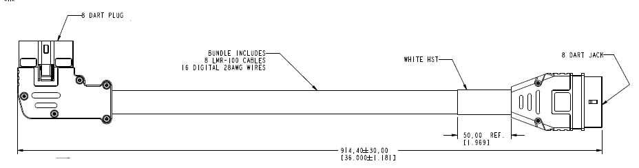
Now, if your scenario requires the antenna to be installed further away from the access point (inside of a freezer for example) there is a 3-feet DART extension cable for that sold by Cisco.
The part number is AIR-CAB003-D8-D8=.
It has 90-degree 8-port plug on one side and straight 8-port jack on the other.
Orientation of Wi-Fi access point with external antenna(s) on Cisco DNA Center maps is represented by 2 key attributes.
Azimuth tells us how many degrees we rotated the antenna around its vertical axis. It ranges from 0 to 360.
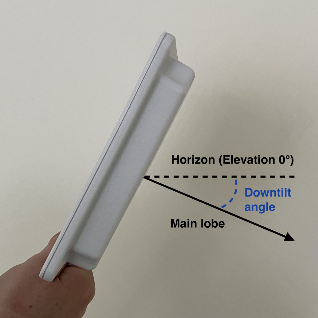
Elevation represents downtilt of the main lobe relative to horizon. It ranges from -90 to 90. Horizon equals to Elevation 0. If the antenna’s downtilt is 30° down, Elevation is -30. The minus sign tells us that the antenna is pointed downwards.
Downtilt of 30° equals to Elevation -30
Antenna shooting above the horizon, which is not very common, would have positive (larger than 0) Elevation value.
We are going to focus exclusively on access points with external antennas in this post. If you are deploying internal antenna AP or AP with dipole antennas, here are the correct settings for you.
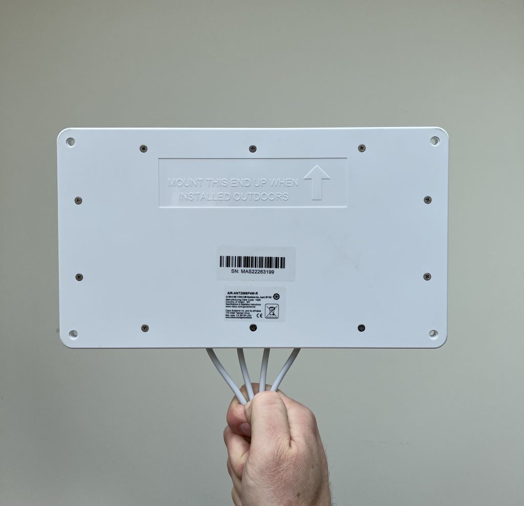
Everything in this post applies to all Cisco’s directional antennas. To name a few, C-ANT9103, C-ANT9104, AIR-ANT2566D4M-R, AIR-ANT2566P4W-R, AIR-ANT2513P4M-N.
Enough theory. Pictures are worth a thousand of words.
We are going to use use Cisco’s AIR-ANT2566P4W-R, which has a nicely squished pattern and changes to its orientation are very visual.
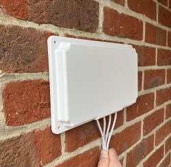
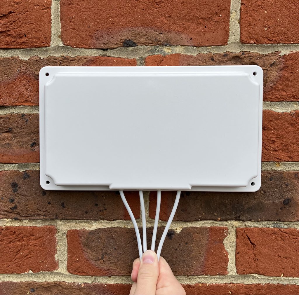
Wall-mounted external antenna
By default DNA Center sets APs with external antennas to Azimuth 0 and Elevation 0. Elevation 0 means that the antenna is wall-mounted (downtilt 0°) and its main lobe shoots parallel to horizon.
Let’s assume perfectly wall-mounted antennas with no downtilt at all in the examples below. That way we don’t need to touch the Elevation setting at all. All we need to do is to adjust the Azimuth angle depending on which wall the antenna is mounted on.
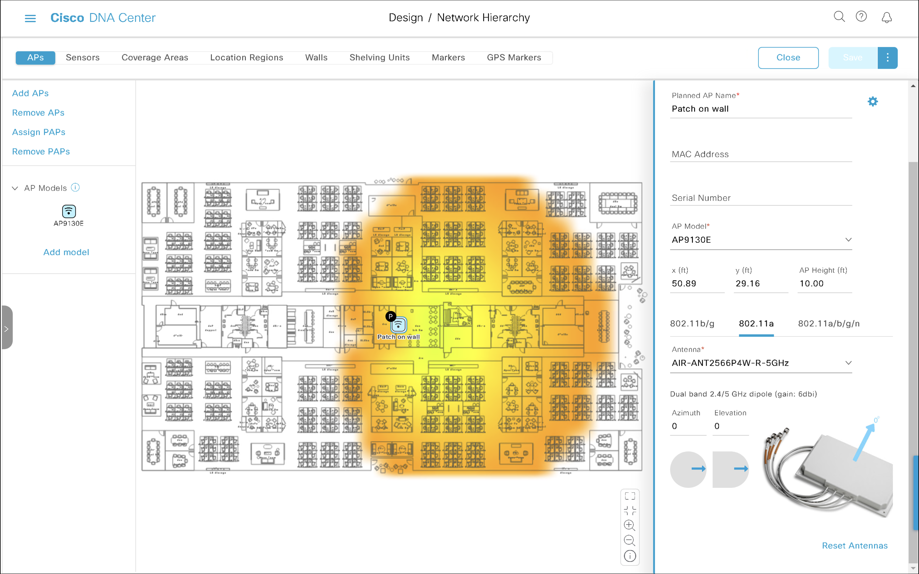
Wall-mounted antenna shooting towards the right
Azimuth 0 and Elevation 0 is the default setting for external antennas. It represents a perfectly wall-mounted antenna (that’s what Elevation 0 means) shooting in the right hand direction (that’s what Azimuth 0 does). The main lobe travels parallel to the floor.
Azimuth 0 and Elevation 0
On the floor plan, it is mounted on the ‘left wall’ of the room, shooting towards the right.
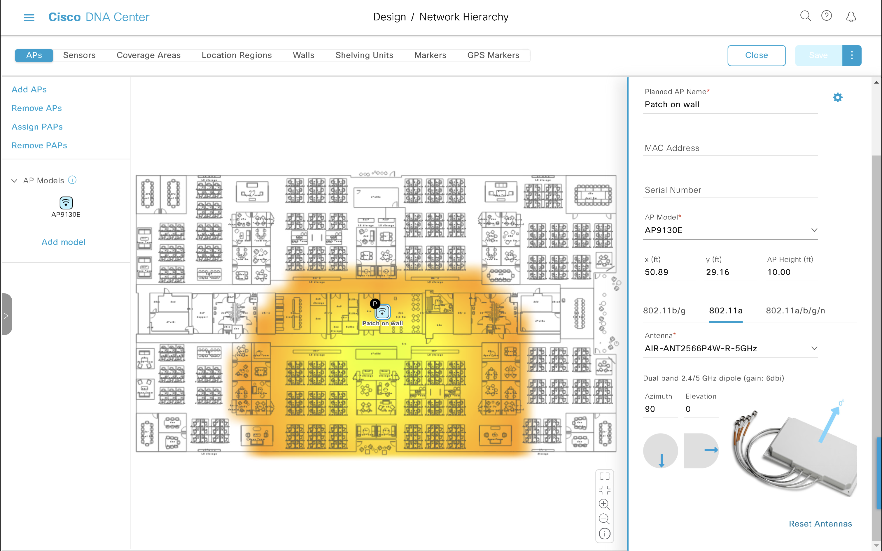
Wall-mounted antenna shooting towards the bottom of the map
Now, what if you installed the antenna on a wall, but it points towards the bottom of the map (I avoid the south as it is not true south) this time?
Azimuth 90 and Elevation 0
We rotated the antenna clockwise around it vertical axis by 90 degrees. There is Azimuth for that, so we will increase Azimuth by 90. The final setting is Azimuth 90 and Elevation 0.
The antenna appears as mounted on the ‘top wall’ of the room shooting towards the bottom of our floor plan.
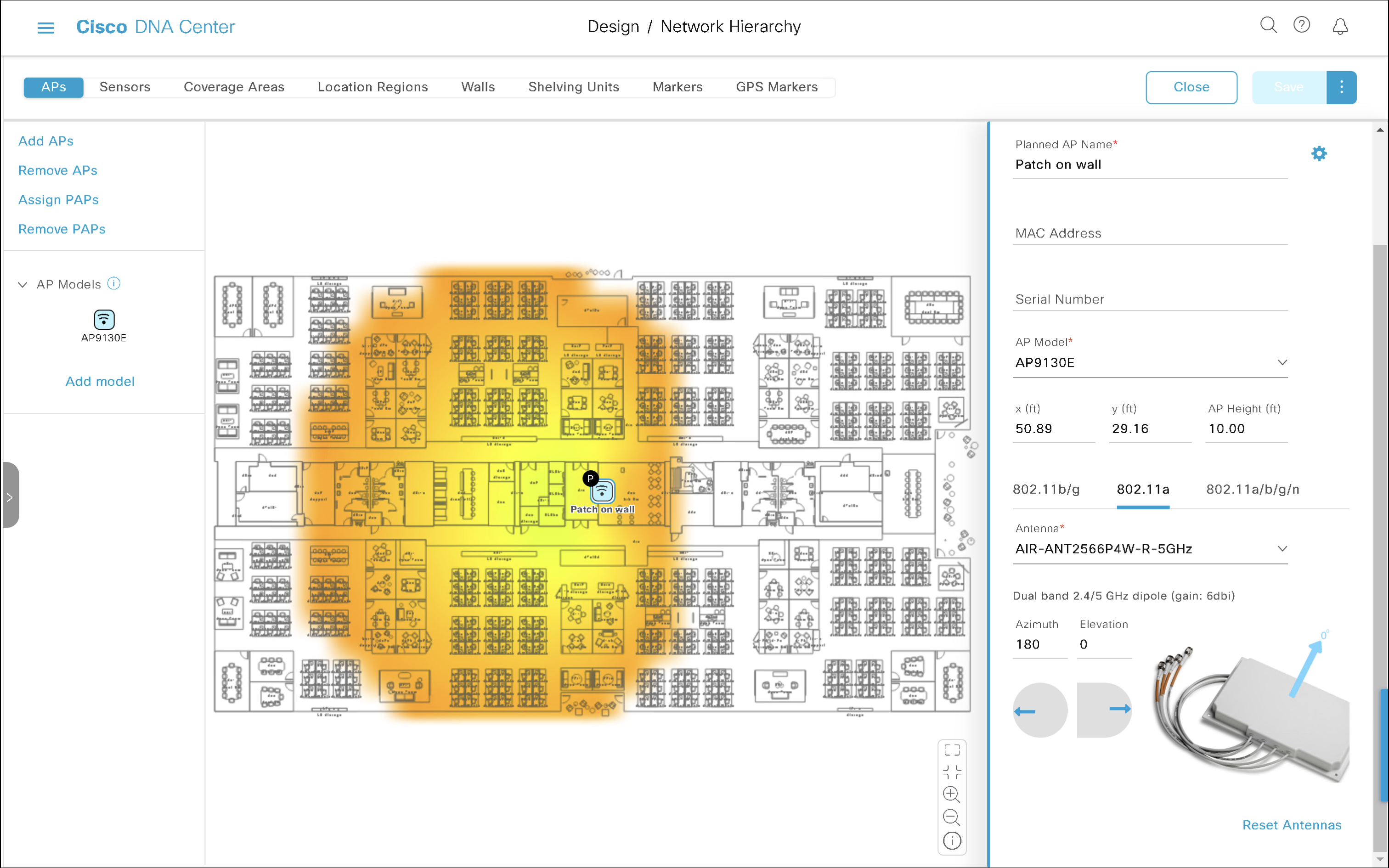
Wall-mounted antenna shooting towards the left
We have now rotated the antenna by another 90 degrees clockwise. That results in Azimuth 180 and Elevation 0.
Azimuth 180 and Elevation 0
It is installed on the right wall pointed towards the left of our floor plan.
Wall-mounted antenna shooting towards the top of the map
Finally, if the antenna is mounted on the ‘bottom wall’ and it points towards the top of our floor plan, that is another 90-degree increment, and results in Azimuth 270 and Elevation 0.
Azimuth 270, Elevation 0
Hopefully, there are no surprises there?
If your antenna uses a different orientation, simply drag the blue Azimuth arrow and point it wherever the antenna’s main lobe is shooting towards.
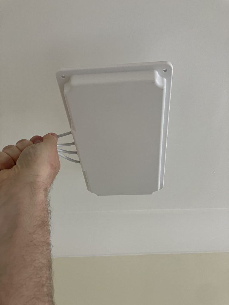
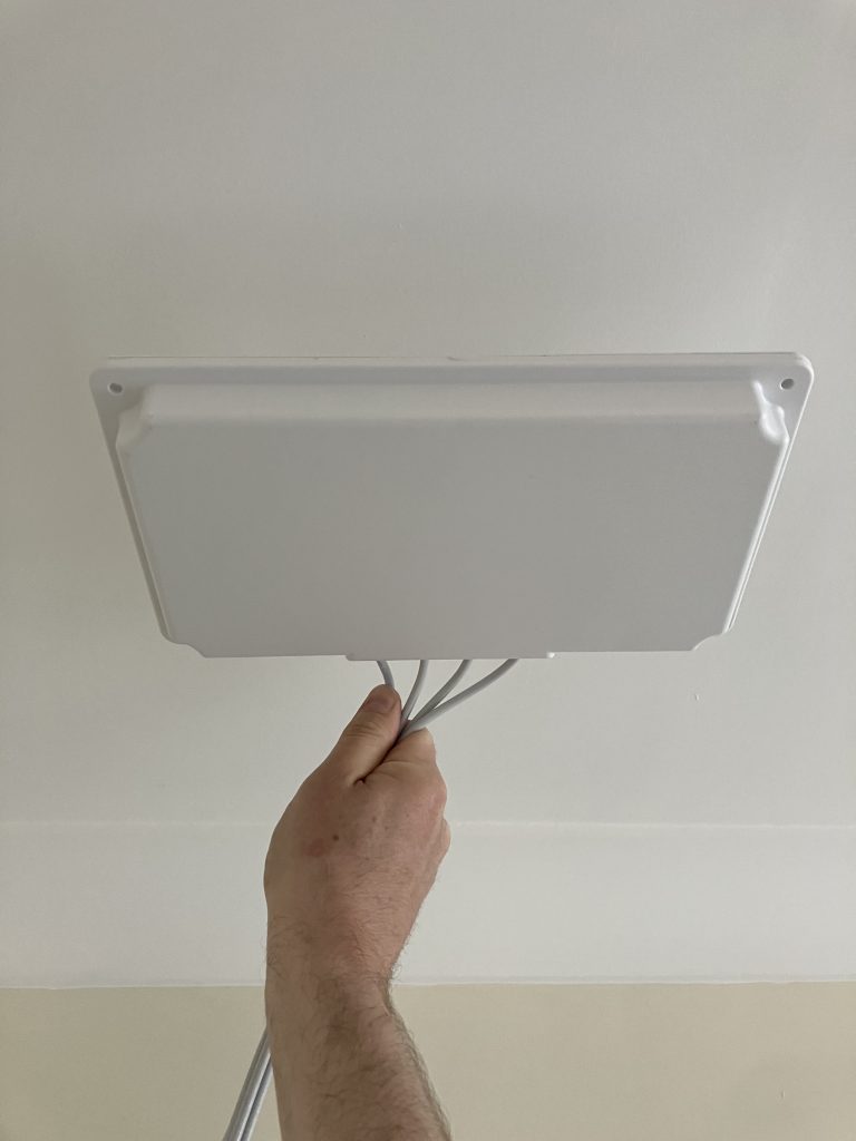
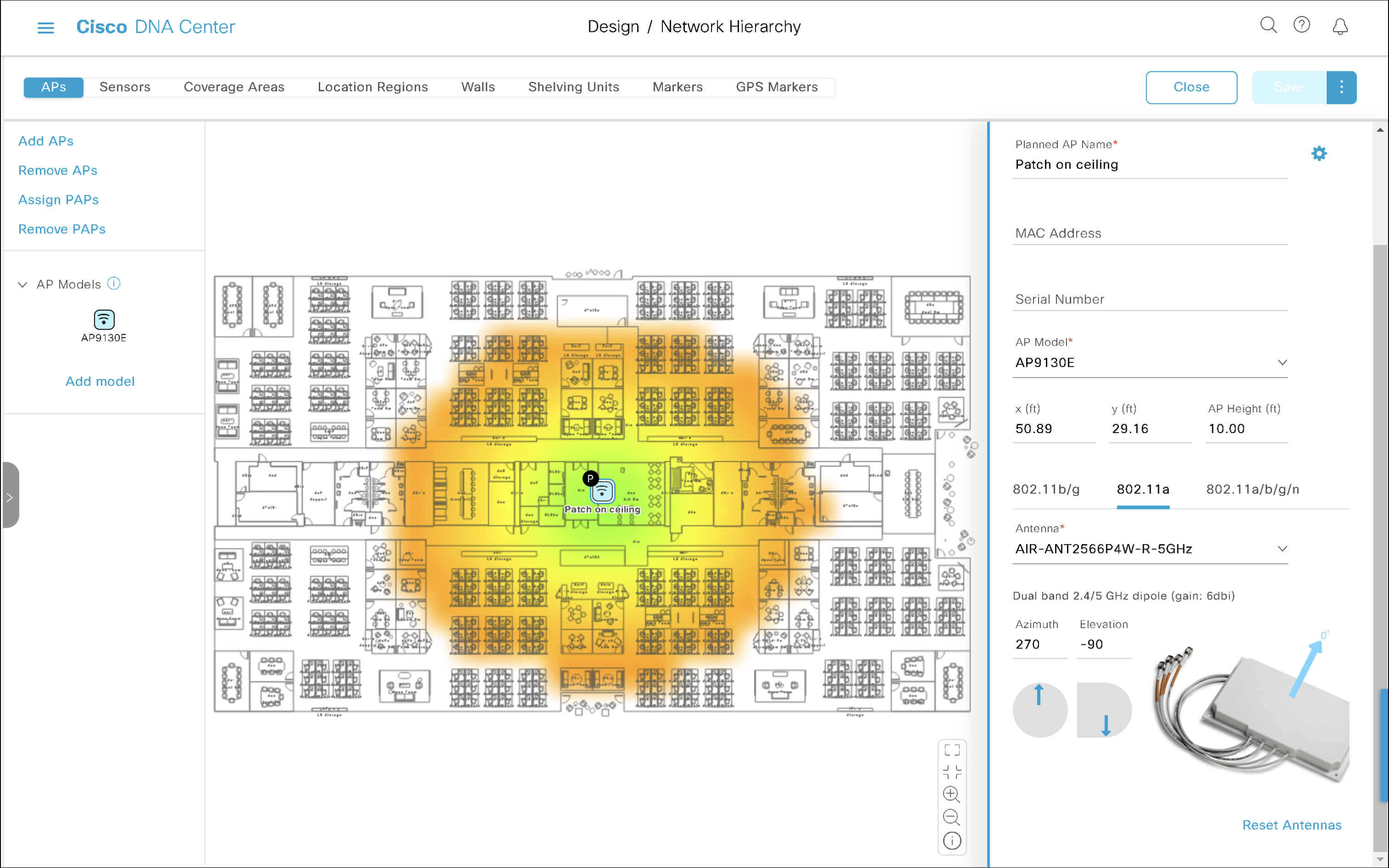
Ceiling-mounted antenna
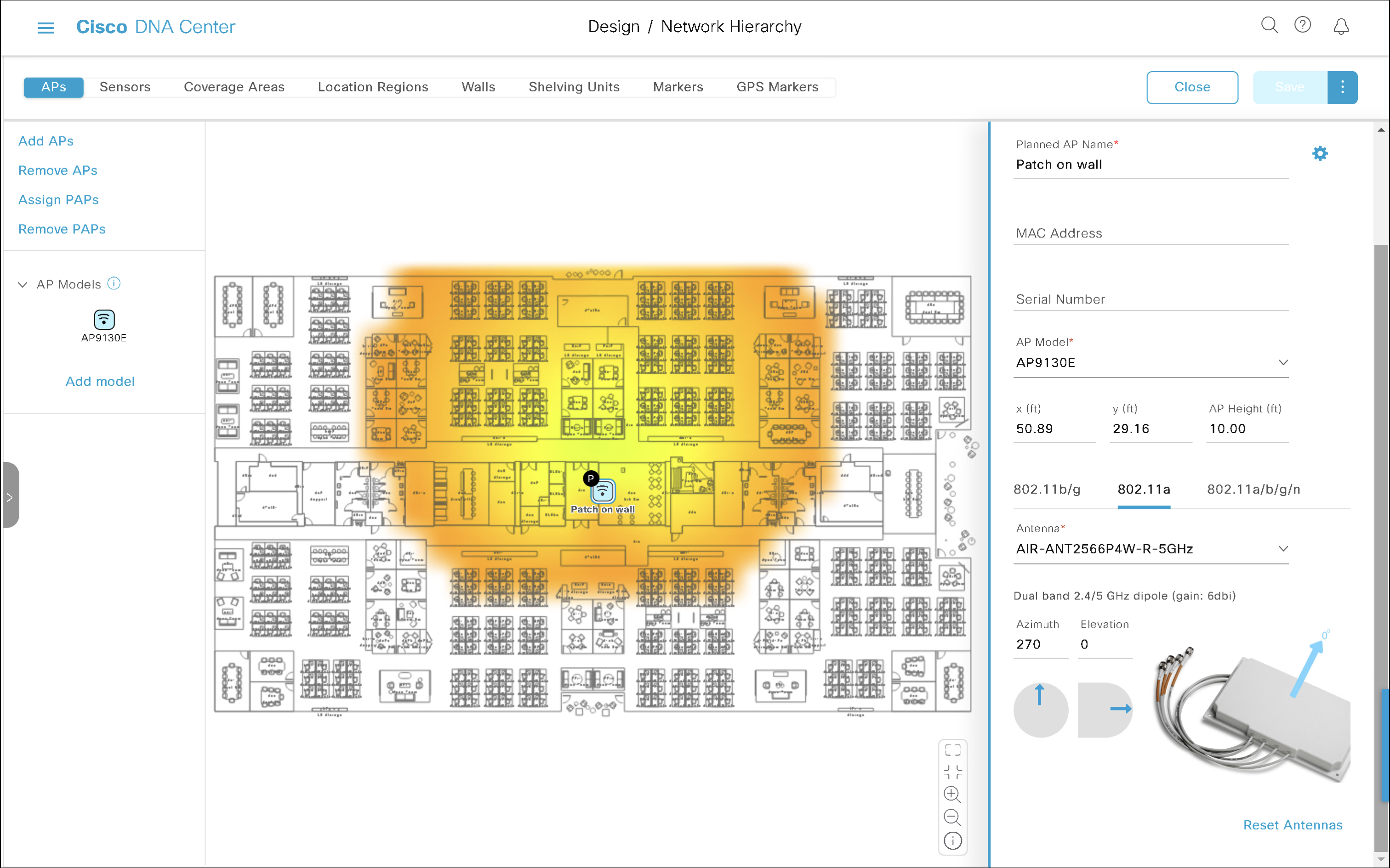
Ceiling-mounted antenna shooting towards the floor
Antenna mounted to the ceiling shooting towards the floor has downtilt of 90°. We simply set Elevation to -90. Don’t miss the minus sign.
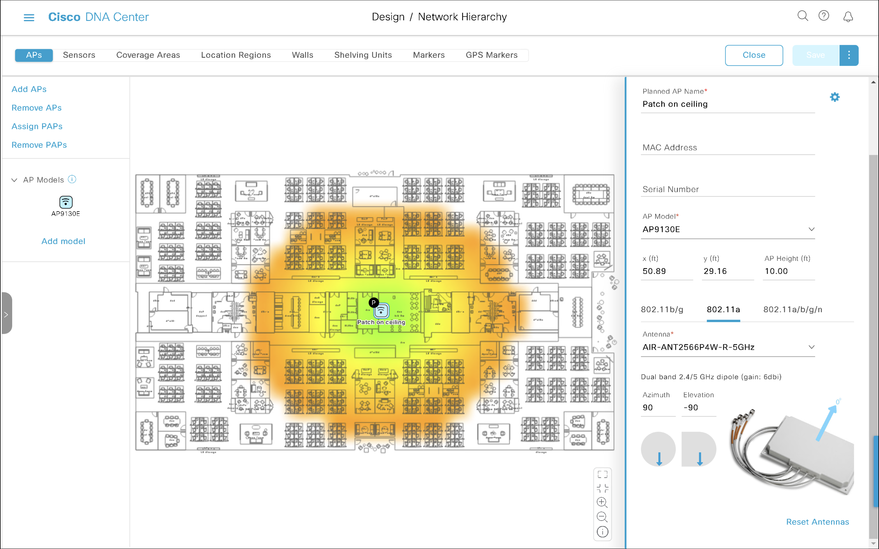
This is how Azimuth 0 (antenna cables on the left, top side of the antenna on the right) and Elevation -90 looks like.
Azimuth 0, Elevation -90
The irregular ‘oval-ish’ pattern of this patch antenna is very obvious on the map. It kisses the top and the bottom of the floor plan.
My antenna is ceiling-mounted but it is rotated?!
To rotate the antenna on the ceiling by 90° clockwise, we just need to increment Azimuth.
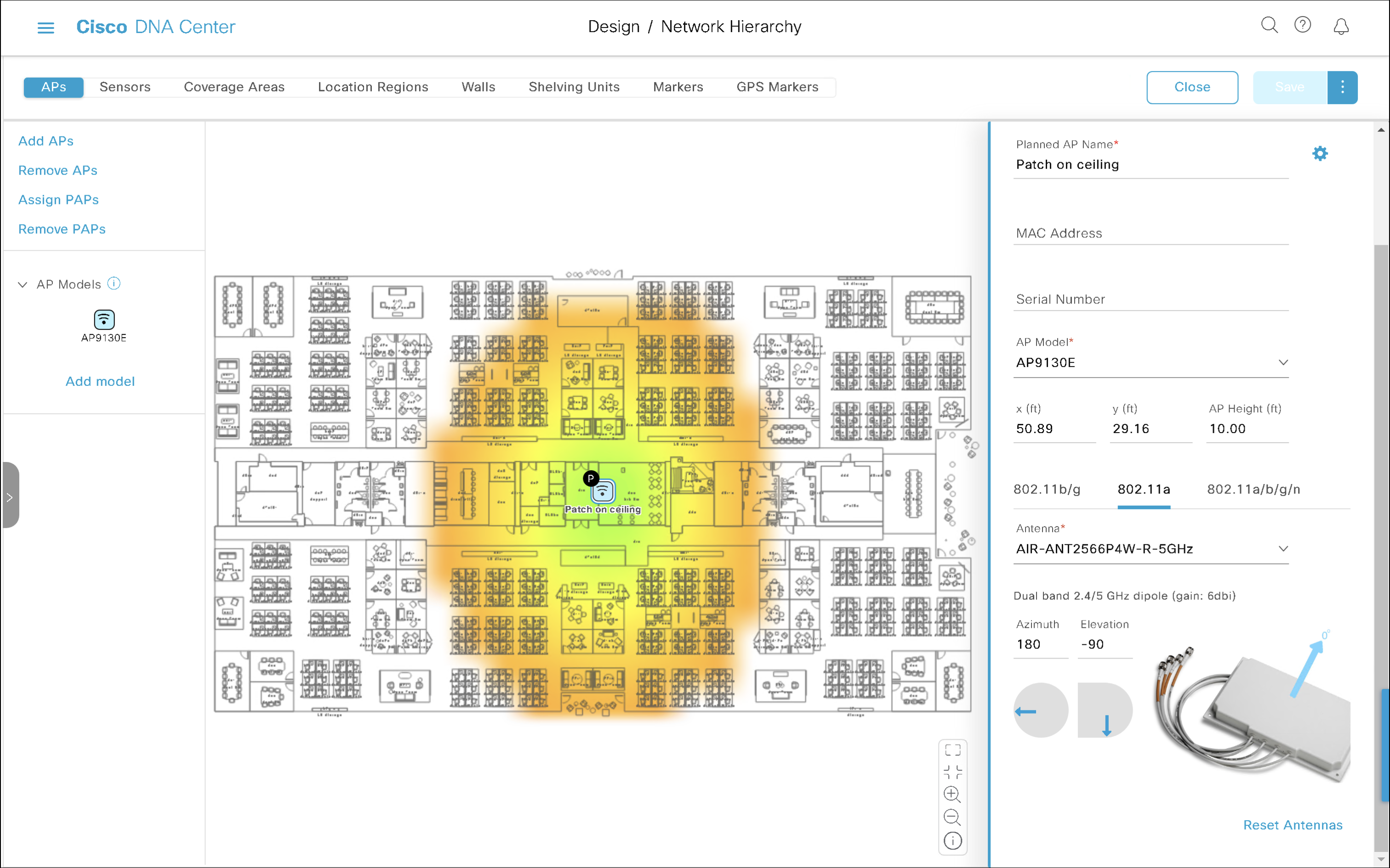
Azimuth 90, Elevation -90
Azimuth 90, Elevation -90
This time the coverage area stretches from left to right, because we rotated the antenna by 90 degrees.
Azimuth 180, Elevation -90
Azimuth 180, Elevation -90
Azimuth 270, Elevation -90
Antenna cables point towards the bottom of the map, which is yet another 90-degree increment. It is still perfectly ceiling-mounted (that’s Elevation -90).
Azimuth 270, Elevation -90
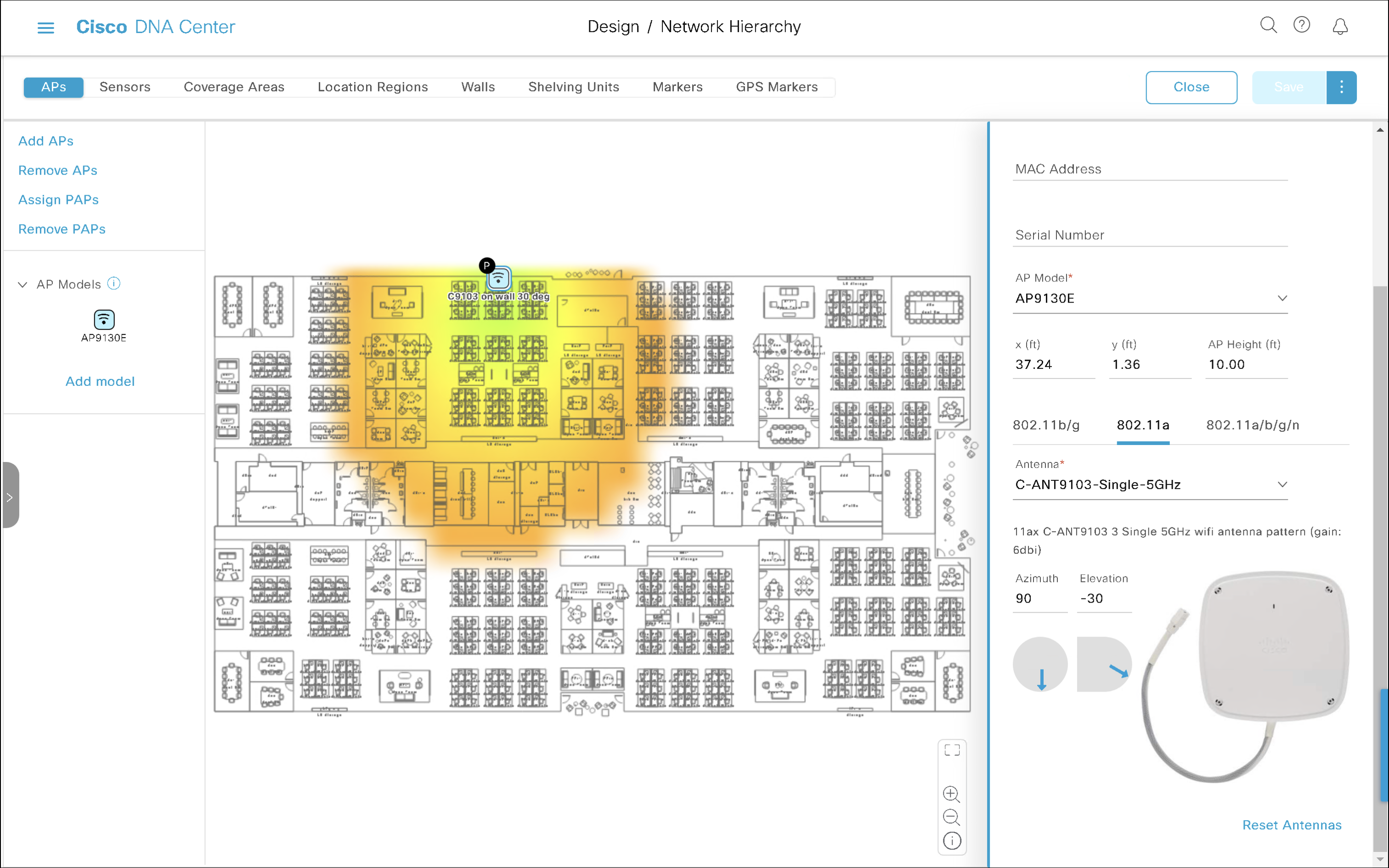
Let’s practise
Now, let’s apply the theory.
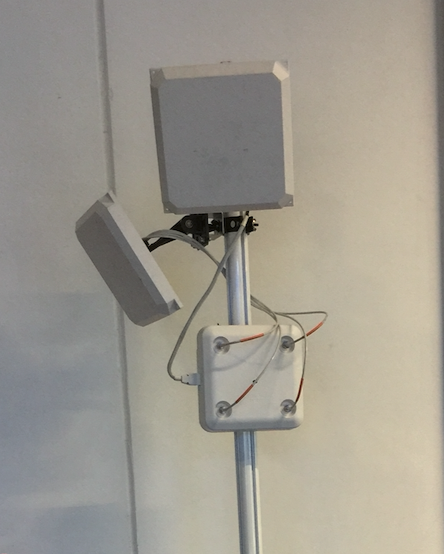
What Azimuth and Elevation would you configure on C-ANT9103 antenna connected to Catalyst 9130 AP mounted using AP-BRACKET-9 bracket on the ‘top wall’ (don’t let the perspective of the photo confuse you) of the floor plan with 30-degree downtilt?
Azimuth 90, Elevation -30
The antenna is mounted on the top wall shooting to the bottom of the map. That translates to Azimuth 90. It is wall-mounted, which normally means Elevation 0, but it is tilted 30° down. So, we subtract 30 from Elevation. And here we go, that’s Elevation -30.
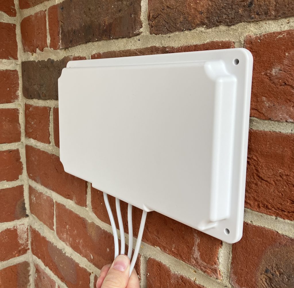
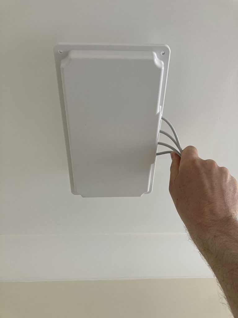
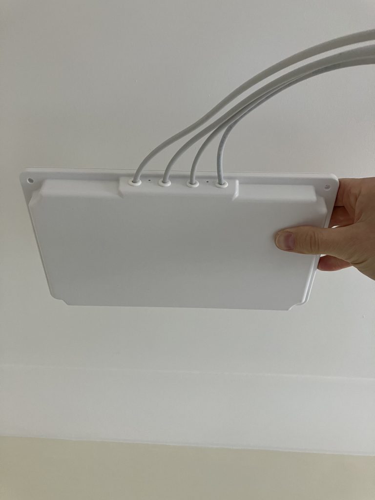
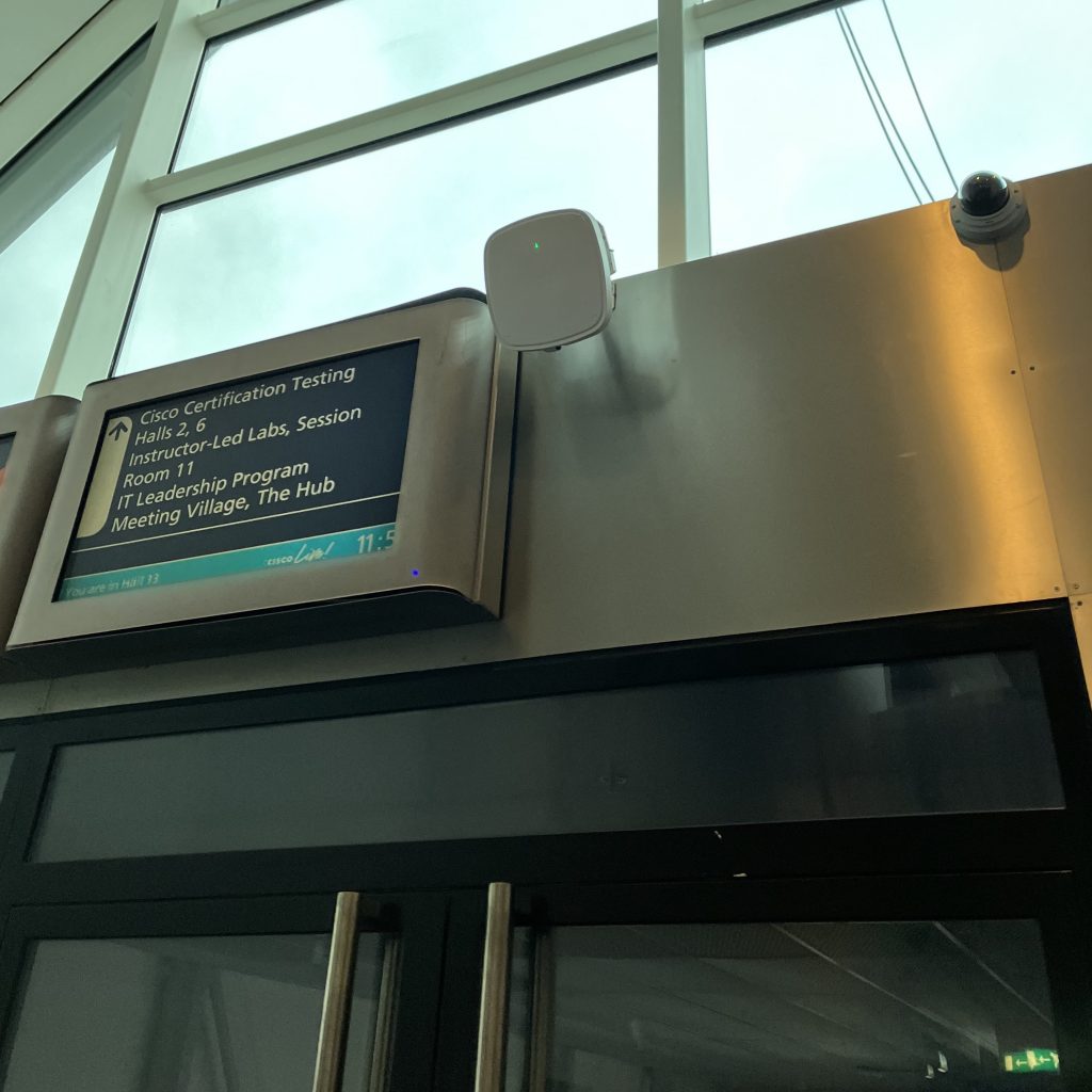
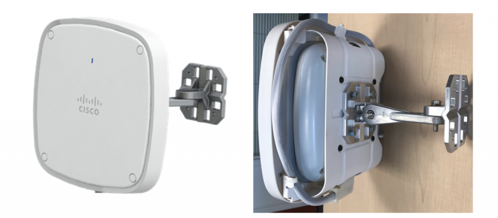
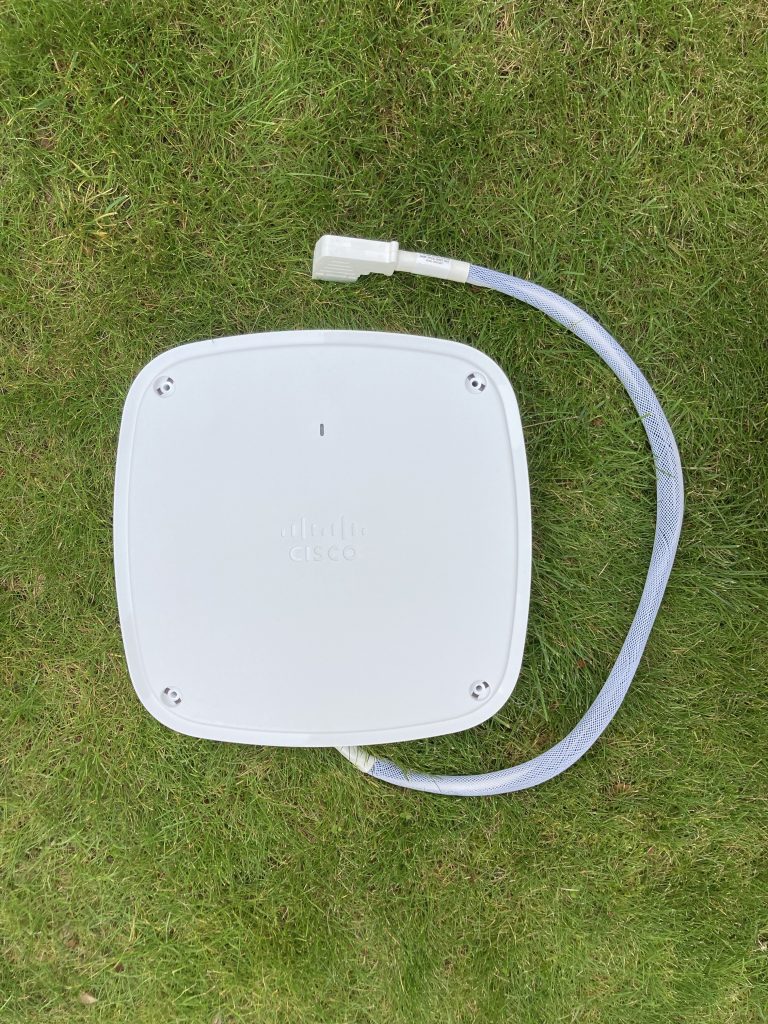
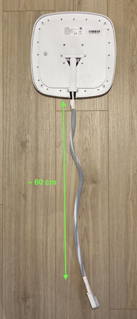
If you have not had a chance to see the new Cisco Catalyst antennas for Catalyst 9130AXE access points, here are a few photos of the C-ANT9103 antenna for your reference.
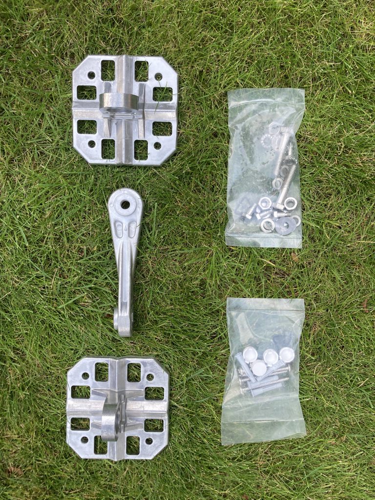
Optionally, you can order an AP + antenna collocation “pocket”, which the Catalyst 9130AXE slides nicely in. It is aesthetically pleasing it, and all it takes to install the AP and antenna is a single mounting bracket. You don’t have to worry about mounting the access point and antenna separately. This drastically simplifies temporary deployments – just think about Cisco Live for example.
The part number is AIR-AP-BRACKET-9=.
Previous generation with a separate AP bracket and antenna bracketThe new collocated, and aesthetically pleasing, solution with AP installed just behind the antenna
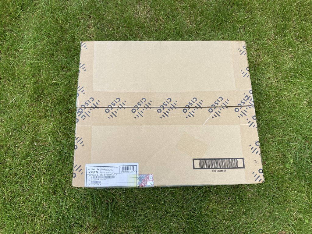
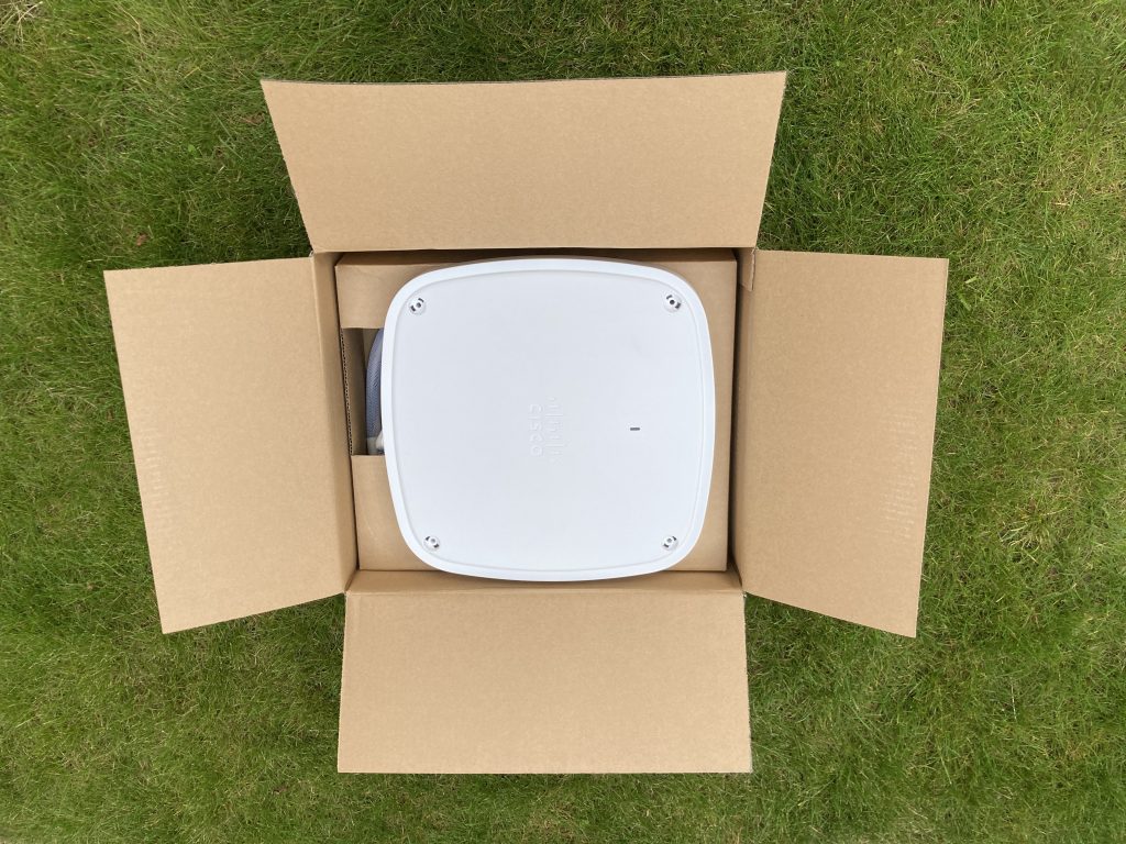
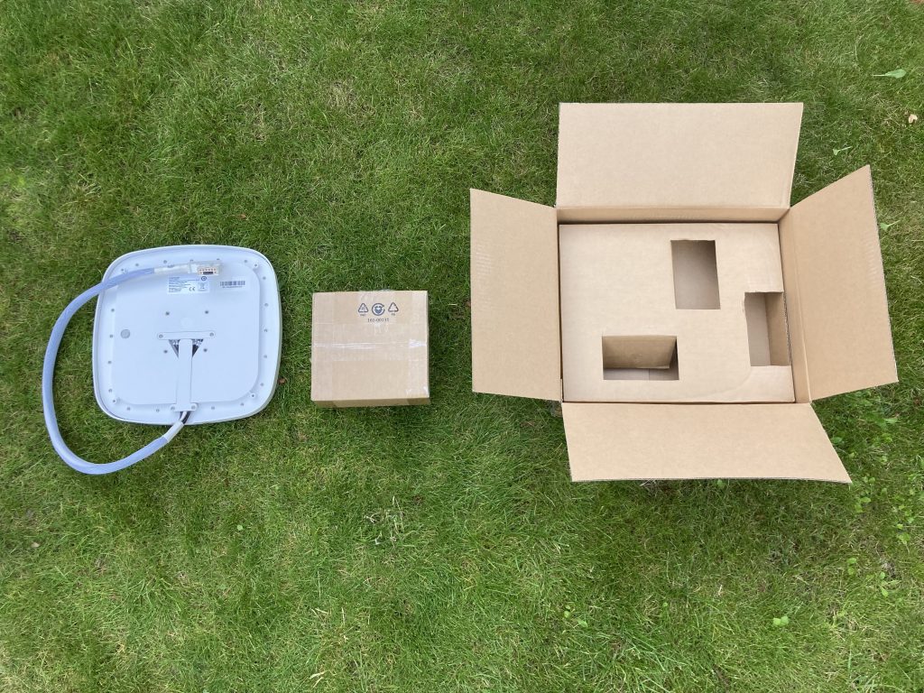
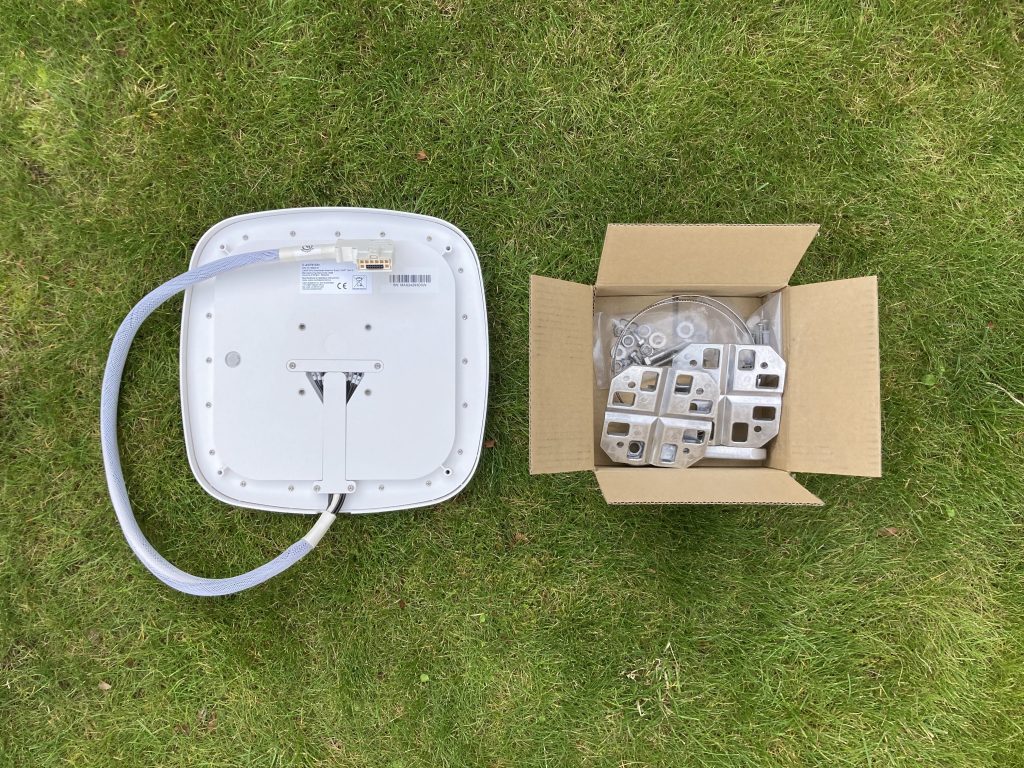
Unboxing
Please always refer to the official Cisco documentation for the latest information and package contents.