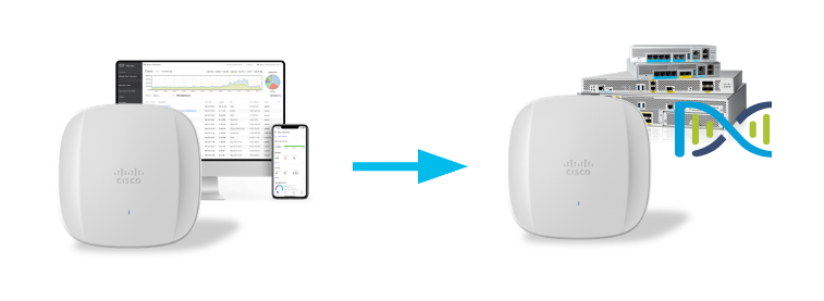
Access point conversion from Catalyst/DNA mode (managed by Catalyst 9800 controller) to Meraki mode allows you to add a Catalyst Wireless AP to Cisco Meraki Dashboard, and fully monitor, and fully manage it from there.
Convert Catalyst/DNA AP to Meraki mode
Order the AP in the right mode
Order your access points in the right mode out of the box, and don’t worry about conversion. That’s the “-MR” SKU for cloud-management/SaaS model. If you wish to manage the APs by a Catalyst 9800 controller, simply find the right access point SKU and regulatory domain based on your coutry using this tool and reach out to your favourite Cisco Partner or distributor for a quote.
What do we need?
Catalyst Wireless CW9162I, CW9164I, CW9166I, CW9166D1, or CW9163E access point joined to a Catalyst 9800 series controller (hardware appliance, cloud instance, or virtual machine)
Cisco Meraki MR access point license
Let’s start the conversion
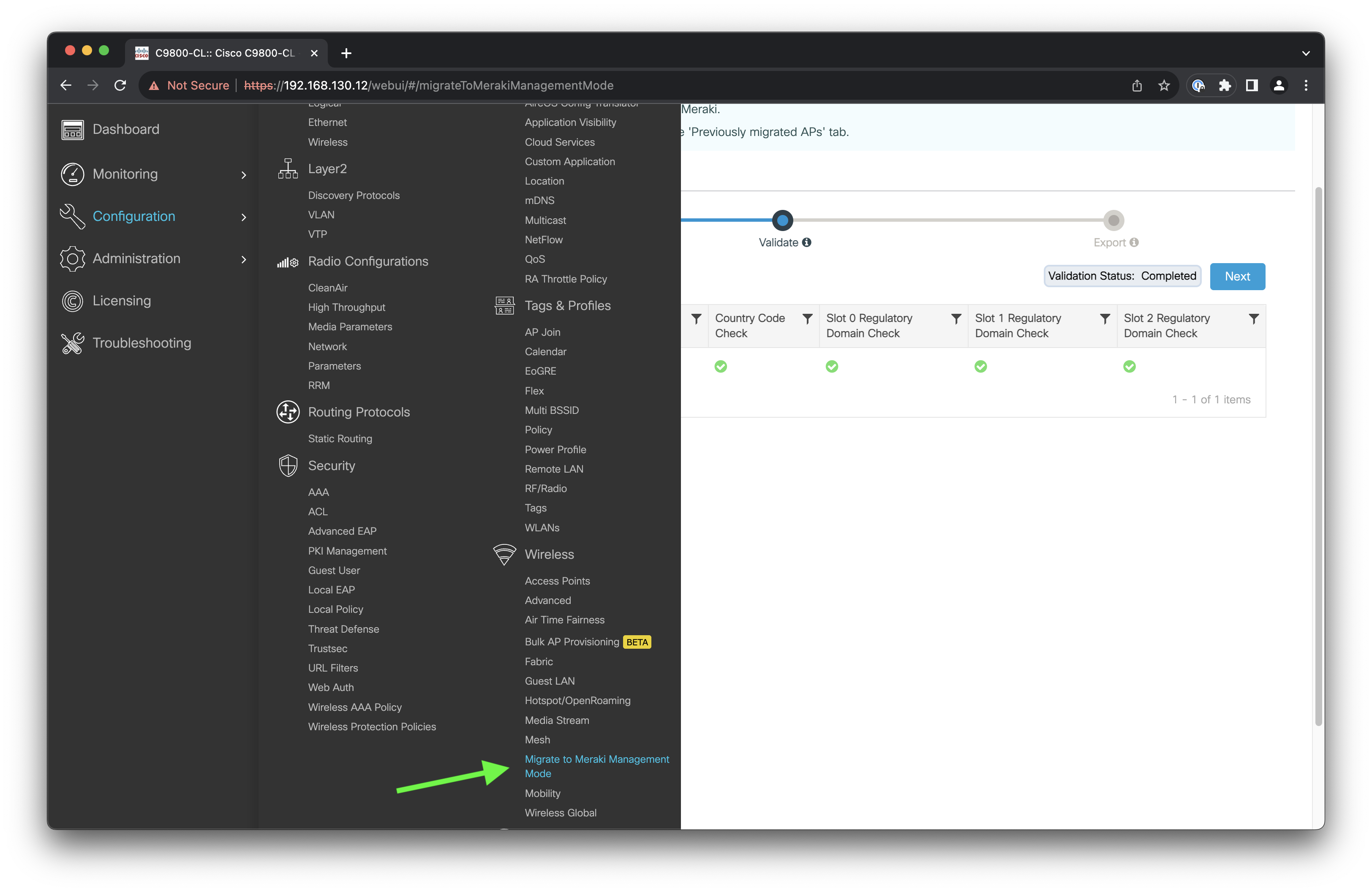
1. Make sure the access points you want to convert have successfully joined the Catalyst 9800 controller. Head over to Configuration > Wireless > Migrate to Meraki Management Mode.
Migrate to Meraki Management Mode
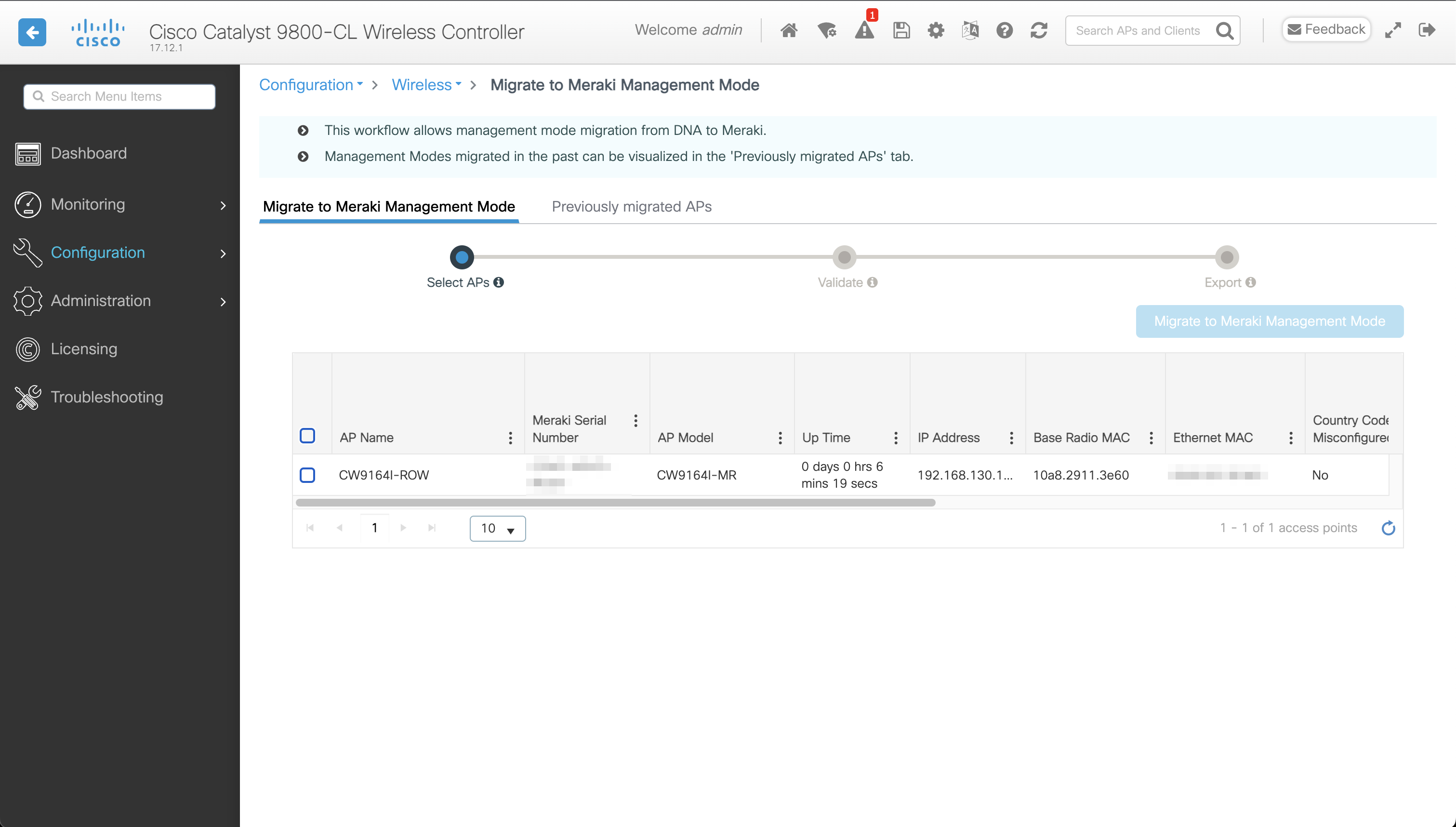
2. Select one or more APs you wish to convert and click the Migrate to Meraki Management Mode button.
Select APs
3. Wait for validation to complete. Click Next.
Validate that the AP can be converted
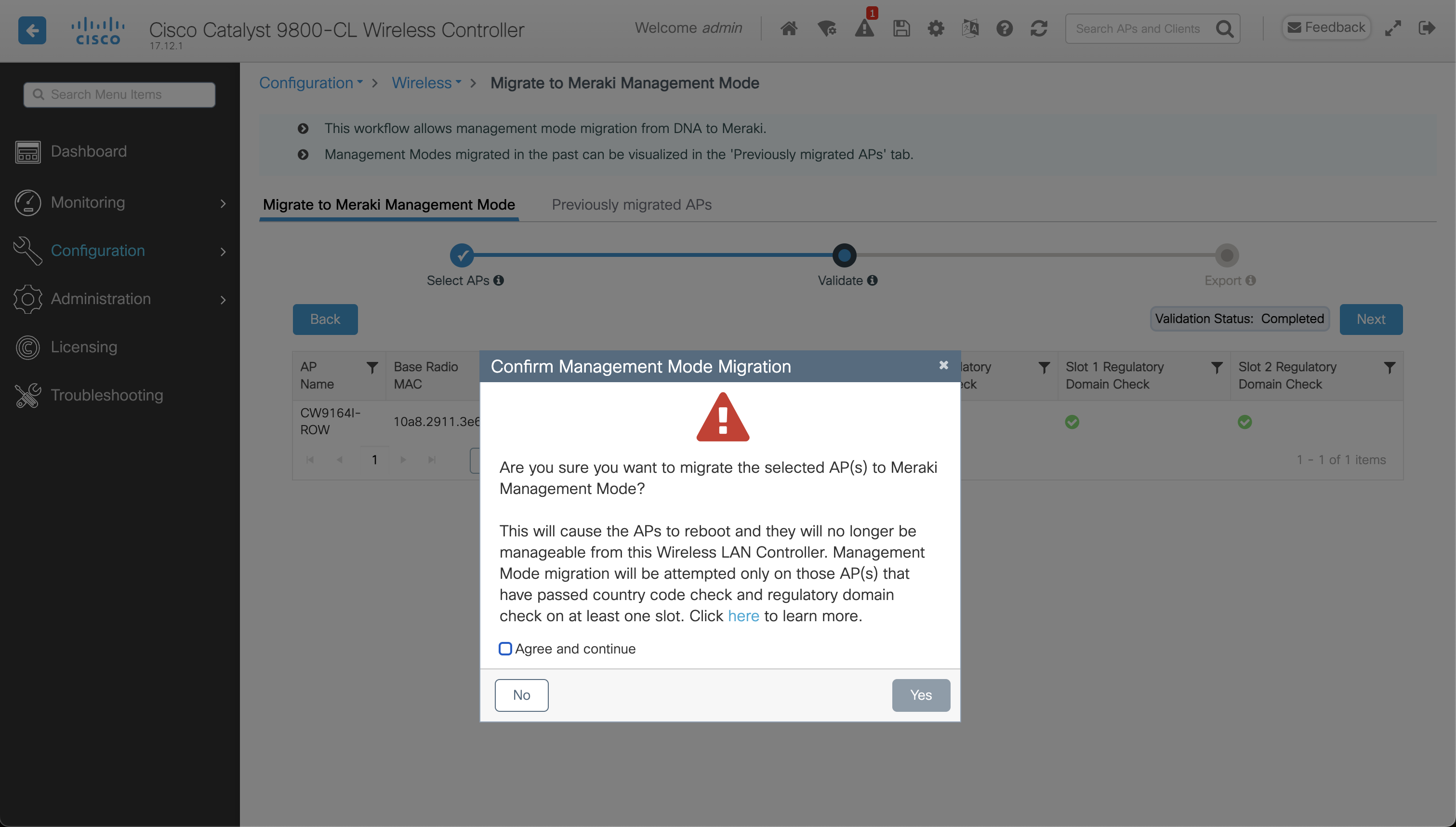
4. Tick Agree and continue and click Yes.
Take a deep breath and kick-start the process
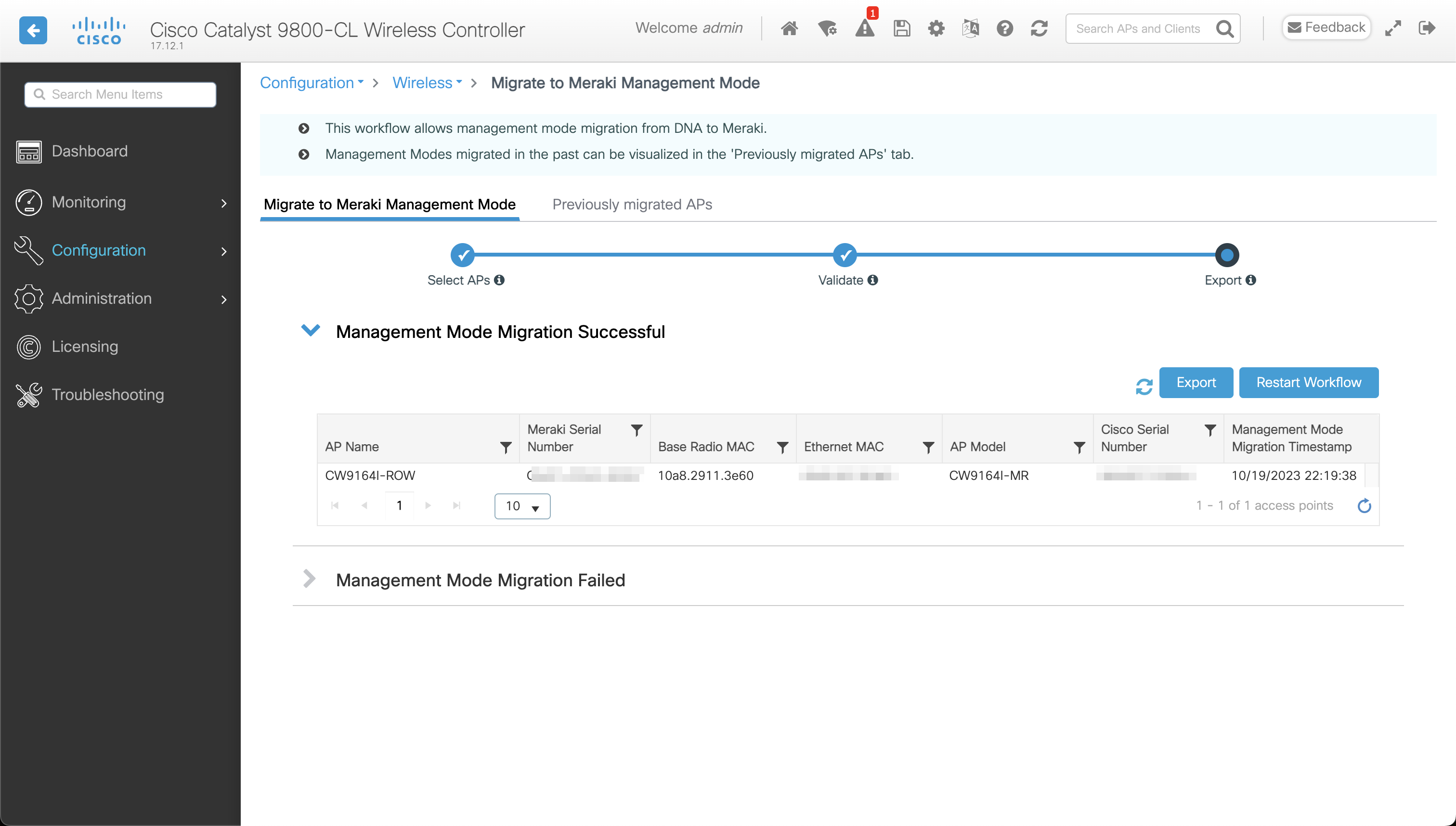
5. Conversion has now finished. Note that each AP has a Cisco Serial Number and Meraki Serial Number. Copy the Meraki Serial Number.
Conversion has finished
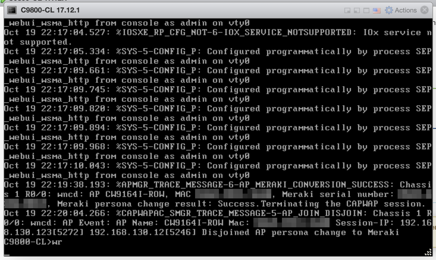
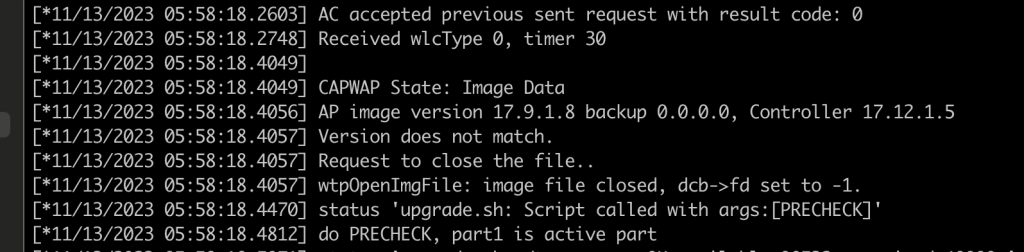
6. While you are doing that, the AP rebooted and started the Meraki image.
AP has left the controller and is about to establish connectivity to Dashboard after reboot
During the boot process, the AP logs a message about the mode change.
Reset reason – AP converted to Meraki mode
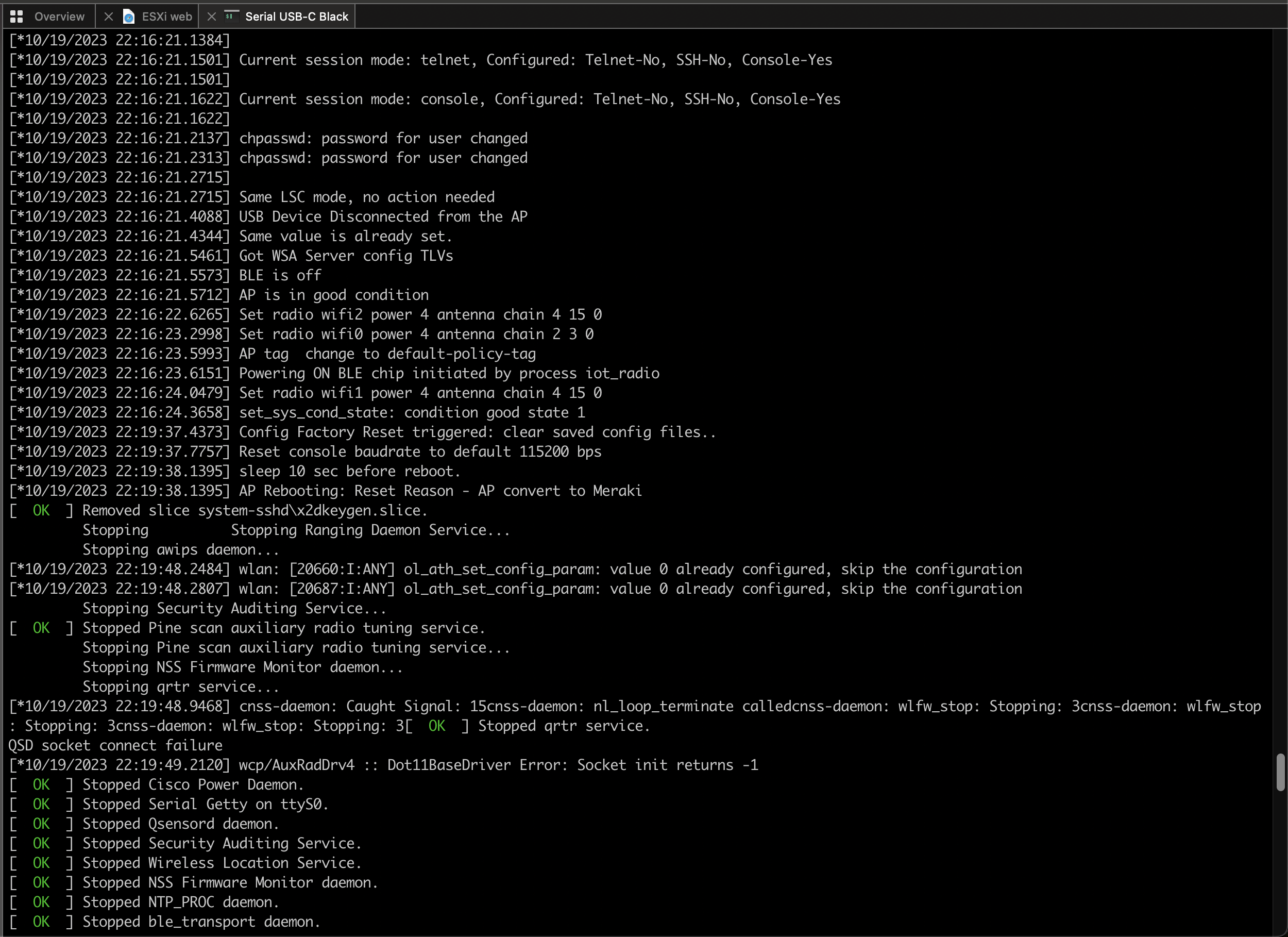
And you will no longer have access to its Console port. If you connect a console cable, <Meraki> output will appear with no option to type any commands.
Console port output after conversion
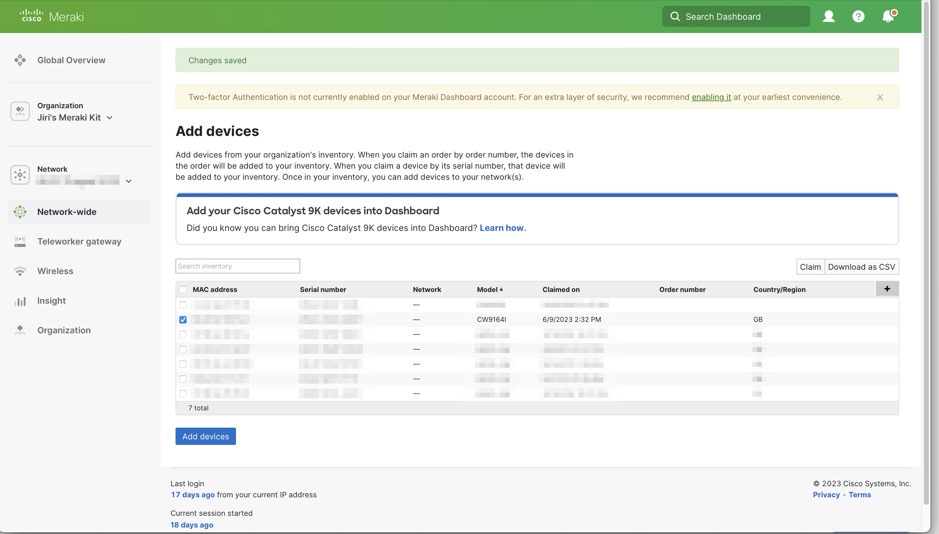
7. Copy the Meraki Serial Number and log in to Cisco Meraki Dashboard. Open Organization > Configure > Inventory. Click Add devices, and paste the Meraki Serial Number of the AP.
InventoryAdd the AP by entering its Meraki Serial Number
8. From now on, the AP now behaves like any other Meraki cloud-managed access point. All monitoring and management features of the Dashboards are available. If you ever change your mind, and wish to convert it back to Catalyst/DNA mode, here is my step-by-step guide.
If you have not used WiFi Explorer before, get yourself a copy of the Pro version here. It is absolutely worth it and extremely useful tool if you have anything to do with Wi-Fi.
The Pro version (the Lite doesn’t) supports Filters. They allow you to filter scan results and get exactly the scan results you are interested in.
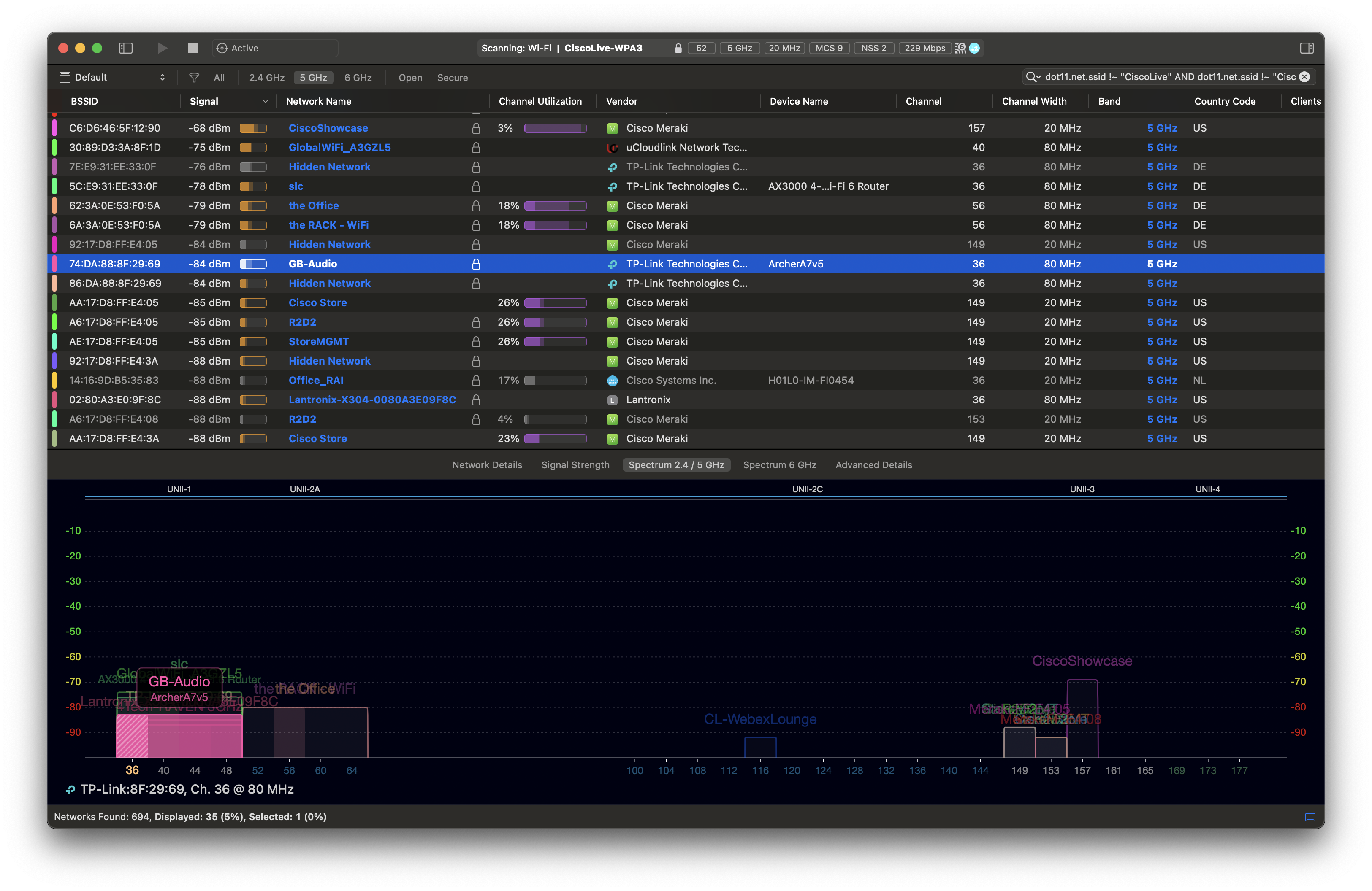
Find rogue access points
Let’s say you want to find APs that use other SSIDs than yours. This filter does just that. It shows all SSIDs other than CiscoLive or CiscoLive-WPA3. Simply paste this string into the Filters text field in the top right-hand corner.
dot11.net.ssid !~ "CiscoLive" AND dot11.net.ssid !~ "CiscoLive-WPA3"
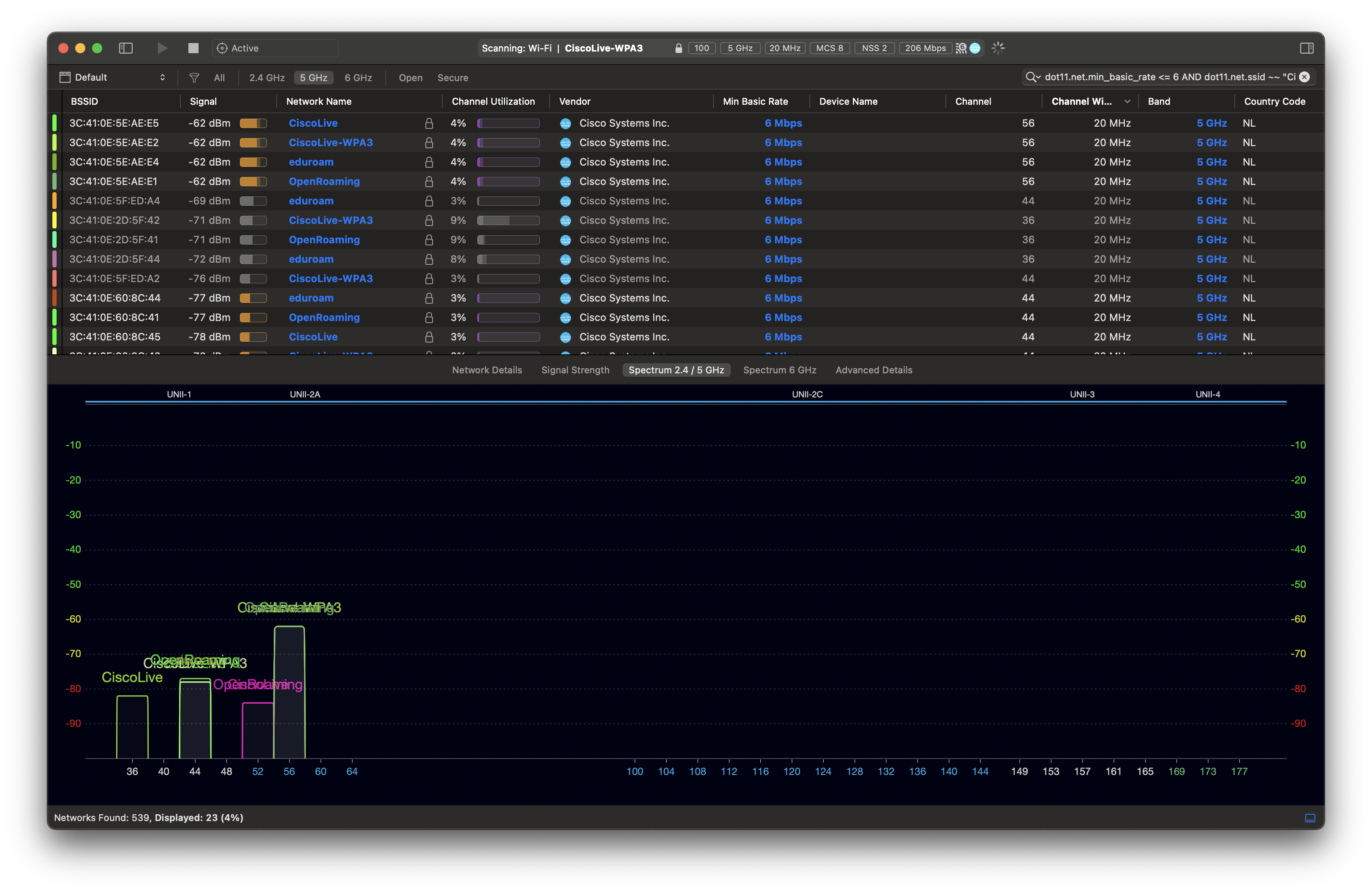
Find APs using low minimum mandatory data rate
Other times you might want to look for access points that have minimum mandatory data rate configured to low – by mistake or by choice. In this example, I am interested in APs broadcasting these 2 SSIDs and using minimum mandatory rate of 6 or lower.
dot11.net.min_basic_rate <= 6 AND dot11.net.ssid ~~ "CiscoLive" OR dot11.net.ssid ~~ "CiscoLive-WPA3"
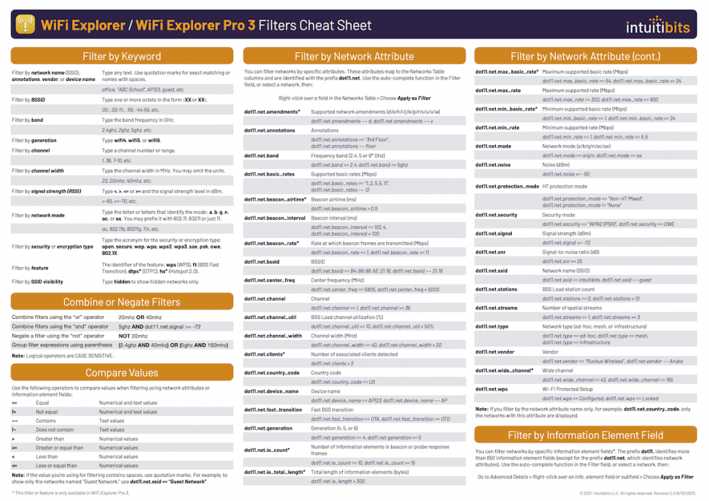
Download the cheat sheet
We have only scratched the surface. You can do so much more with filters.
Intuitibits, the makers of WiFi Explorer, published a great one-pager documenting the syntax. Get yourself a copy.
The latest generation of Wi-Fi 6E Catalyst Wireless access points (CW9162, CW9164, CW9166 series) gives you the option to either cloud-manage them using Cisco Meraki Dashboard, or manage the APs by Cisco Catalyst 9800 series Wireless LAN Controller (WLC).
They are the exact same hardware and they ship pre-loaded with the Catalyst/DNA and Meraki software image. Depending on the mode setting, they either boot one image or the other.
What do we need
Catalyst Wireless CW9162I, CW9164I, CW9166I, CW9166D1, CW9163E access point in Meraki mode
Cisco Meraki MR access point license to perform the conversion
Cisco DNA Essentials or DNA Advantage access point license if you want to use join and manage the AP by a Catalyst 9800 controller
Choose AP mode before ordering
You will have the best experience when you order your access points in the right mode.
Order the right mode
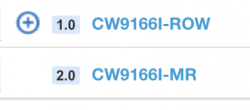
Order a DNA persona AP and it will auto-discover your Catalyst 9800 controller using one of the supported methods. In the UK, I can order the “-ROW” AP and manage it by Catalyst 9800, and optionally add Catalyst Center (previously known as DNA Center) to get analytics, assurance and other great features. Find the right access point SKU and regulatory domain based on your coutry using this tool.
If you prefer, order the Meraki mode access point, connect it to the internet, and claim it in the Dashboard. Meraki APs use a single “-MR” SKU globally.
Conversion from MR to Catalyst/DNA mode
If you ordered a Meraki access point and your requirements have changed, you can convert the AP to DNA mode.
1. Make sure you have an active Meraki MR license. Why? We need the license to connect the AP to Dashboard, and to open a conversion request with Meraki technical support team.
2. Provide power and internet connectivity to the access point.
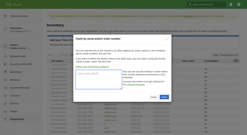
3. Log in to Dashboard. Navigate to Organization > Configure > Inventory and add the access point using its Meraki S/N.
Enter the Meraki S/N from the product label
4. Add your MR license to Dashboard under Organization > Configure > License Info.
5. Wait for the AP to connect to Dashboard and change its LED to solid green or solid blue. Perfect, the AP is now online.
6. Complete this checklist first. Disable Meshing feature and make sure your Catalyst 9800 is ready for the AP to connect after conversion has completed.
Disable Meshing feature
7. Open a new support case by clicking the (?) question mark in the top right hand corner > Cases > New Case.
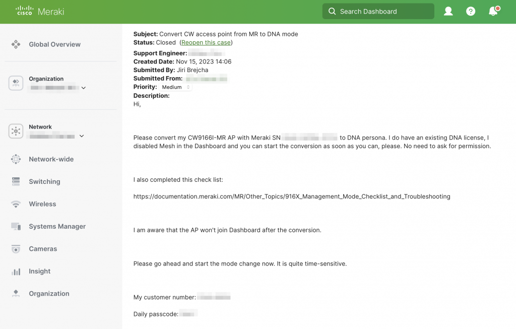
8. Include all these details to speed up the conversion process. Find your Customer Number by clicking the person icon in the top right hand corner. To get your Daily Support Code, click the same person icon, then open My profile.
Hi,

Please convert my CW*****-MR AP with Meraki SN ****-****-**** to DNA mode. I do have an existing DNA license. I disabled Meshing in the Dashboard.

I have completed this checklist:
https://documentation.meraki.com/MR/Other_Topics/916X_Management_Mode_Checklist_and_Troubleshooting

I am aware that the AP will not join Dashboard after the conversion, unless I convert it back to MR mode.

Please go ahead and start the mode change immediately.

My customer number: ****-****
My support passcode for today: ****

Have a great day!
9. If this conversion is urgent, call into Meraki support. No, don’t e-mail the support team, call them. Have the case number by hand. Find the best phone number here.
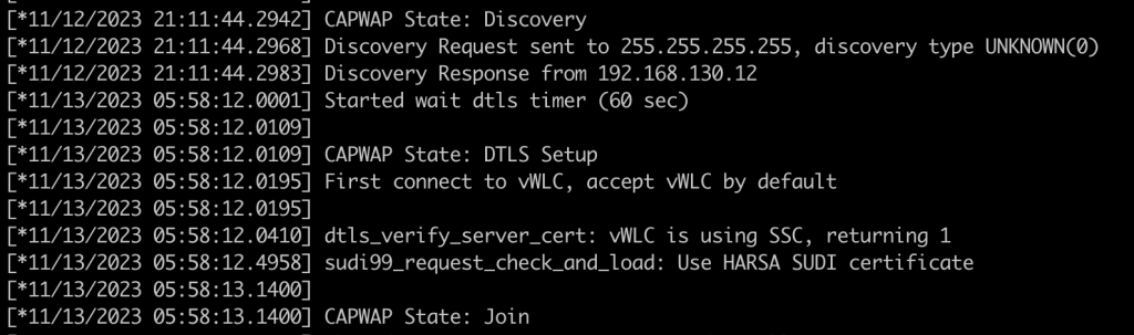
10. After the support engineer starts the conversion, your AP will reboot. It is now in the Catalyst mode. You can verify that by keeping an eye on the Console port output during its boot. Just to remind you (and myself): The new Console port baud rate is 115200 from 17.12.1 release onwards.
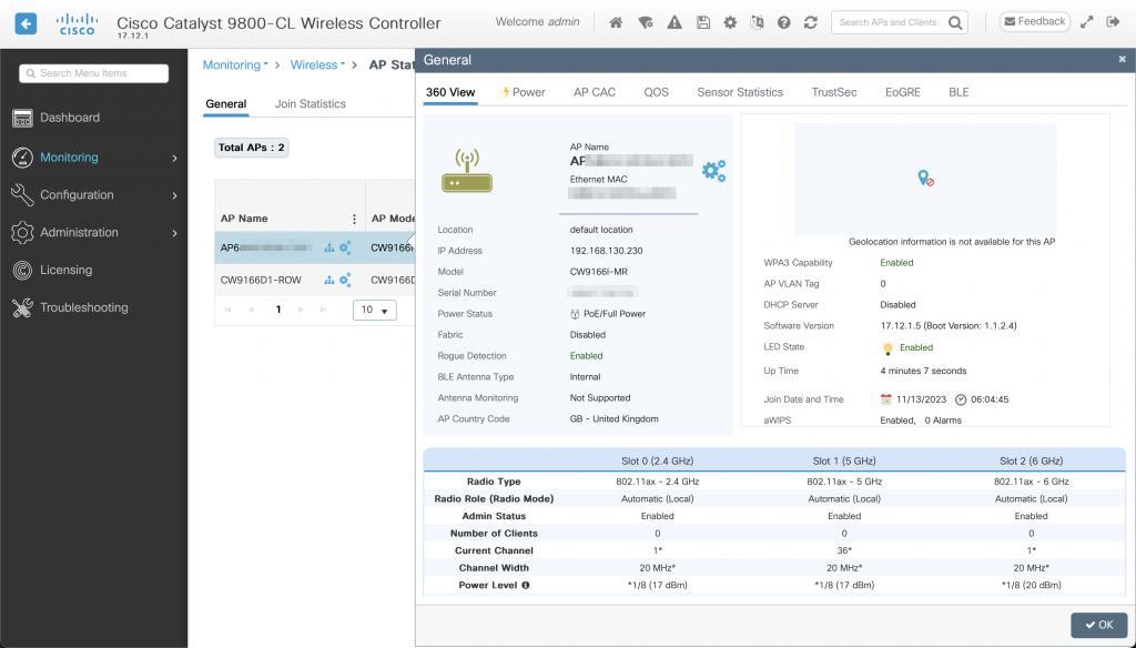
12. Our DHCP server assigned an IP address to the AP, which has automatically discovered and joined the WLC located in the same IP subnet.
Successful WLC discovery and AP joinFollowed by automatic software image upgradeThe AP has joined the WLC and is ready for use
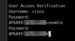
To enable SSH and Console access, create a username, password and enable password in the Catalyst 9800 controller’s AP Join Profile > Management > User section. SSH protocol is disabled by default. You can enable it in the AP Join Profile.
You have full Console access and control over the AP
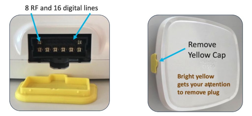
Cisco’s Catalyst 9130AXE access point (the external antenna model) doesn’t have any antennas built-in by design. It uses a DART connector with 8 RF lines and 16 digital lines. They carry the RF signals and allow communication between the AP and antenna.
All new C-ANT9101, C-ANT9102 and C-ANT9103 antennas connect natively using their directly-attached DART connector to the Catalyst 9130AXE access point. It significantly simplifies the deployment process, allows the AP to automatically detect the antenna model, type and gain, and it doesn’t allow any room for installation errors like loose RP-TNC connectors or swapped antenna RF ports.
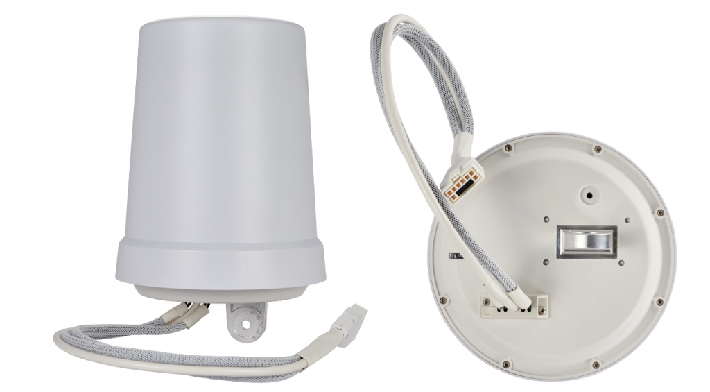
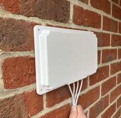
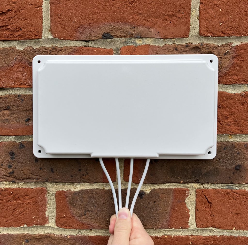
Here is an example of the new bell antenna C-ANT9102 with directly-attached DART connector.
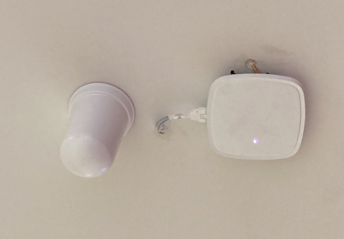
And here is one connected to the C9130AXE-E access point.
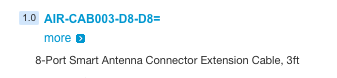
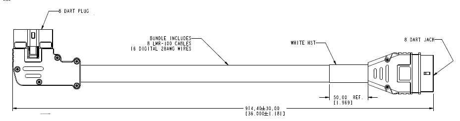
Now, if your scenario requires the antenna to be installed further away from the access point (inside of a freezer for example) there is a 3-feet DART extension cable for that sold by Cisco.
The part number is AIR-CAB003-D8-D8=.
It has 90-degree 8-port plug on one side and straight 8-port jack on the other.
Orientation of Wi-Fi access point with external antenna(s) on Cisco DNA Center maps is represented by 2 key attributes.
Azimuth tells us how many degrees we rotated the antenna around its vertical axis. It ranges from 0 to 360.
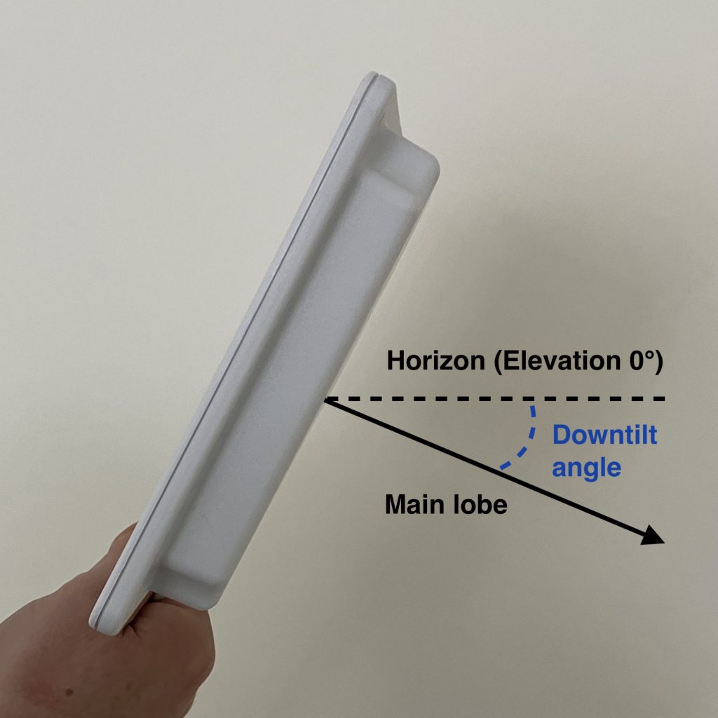
Elevation represents downtilt of the main lobe relative to horizon. It ranges from -90 to 90. Horizon equals to Elevation 0. If the antenna’s downtilt is 30° down, Elevation is -30. The minus sign tells us that the antenna is pointed downwards.
Downtilt of 30° equals to Elevation -30
Antenna shooting above the horizon, which is not very common, would have positive (larger than 0) Elevation value.
We are going to focus exclusively on access points with external antennas in this post. If you are deploying internal antenna AP or AP with dipole antennas, here are the correct settings for you.
Everything in this post applies to all Cisco’s directional antennas. To name a few, C-ANT9103, C-ANT9104, AIR-ANT2566D4M-R, AIR-ANT2566P4W-R, AIR-ANT2513P4M-N.
Enough theory. Pictures are worth a thousand of words.
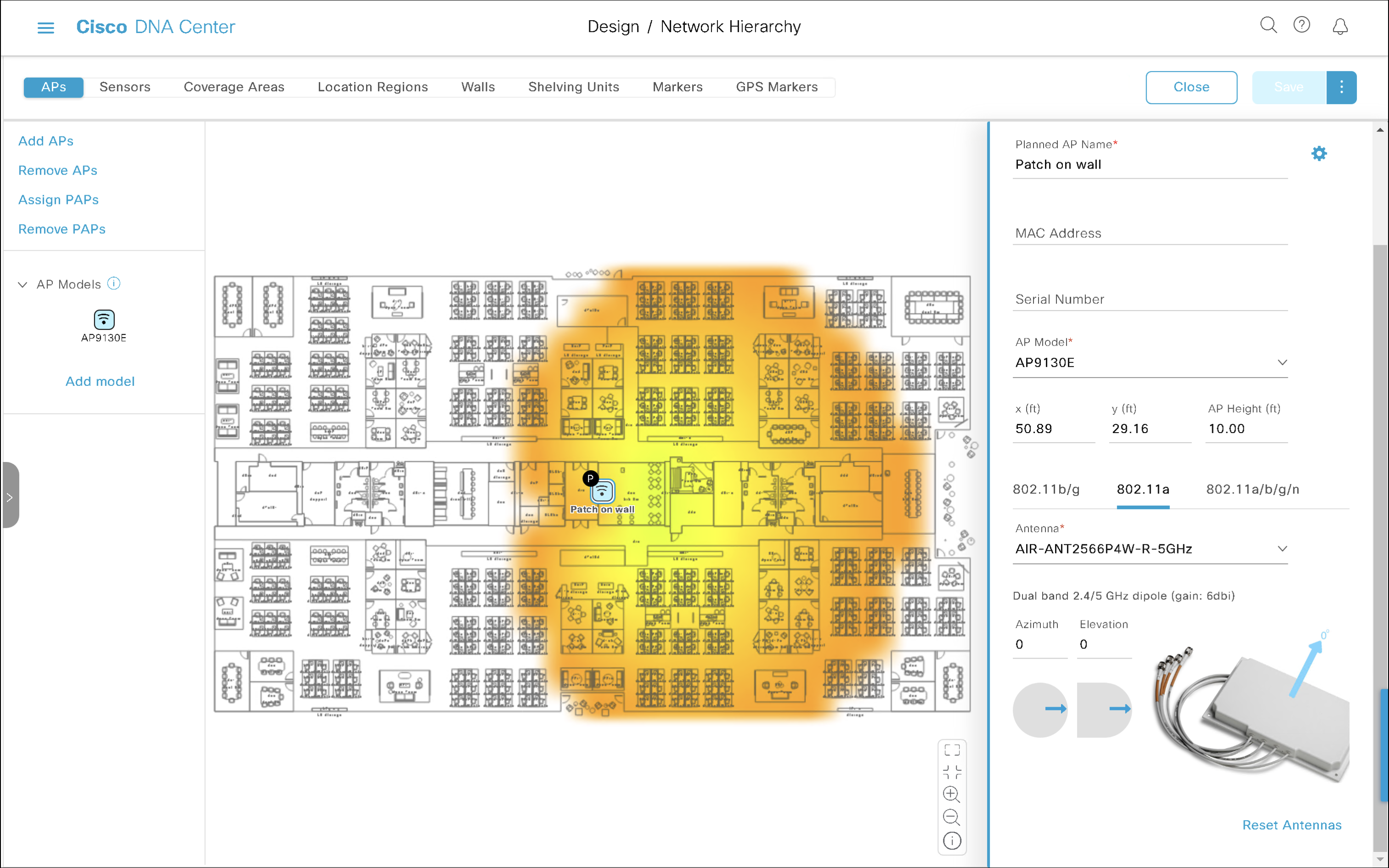
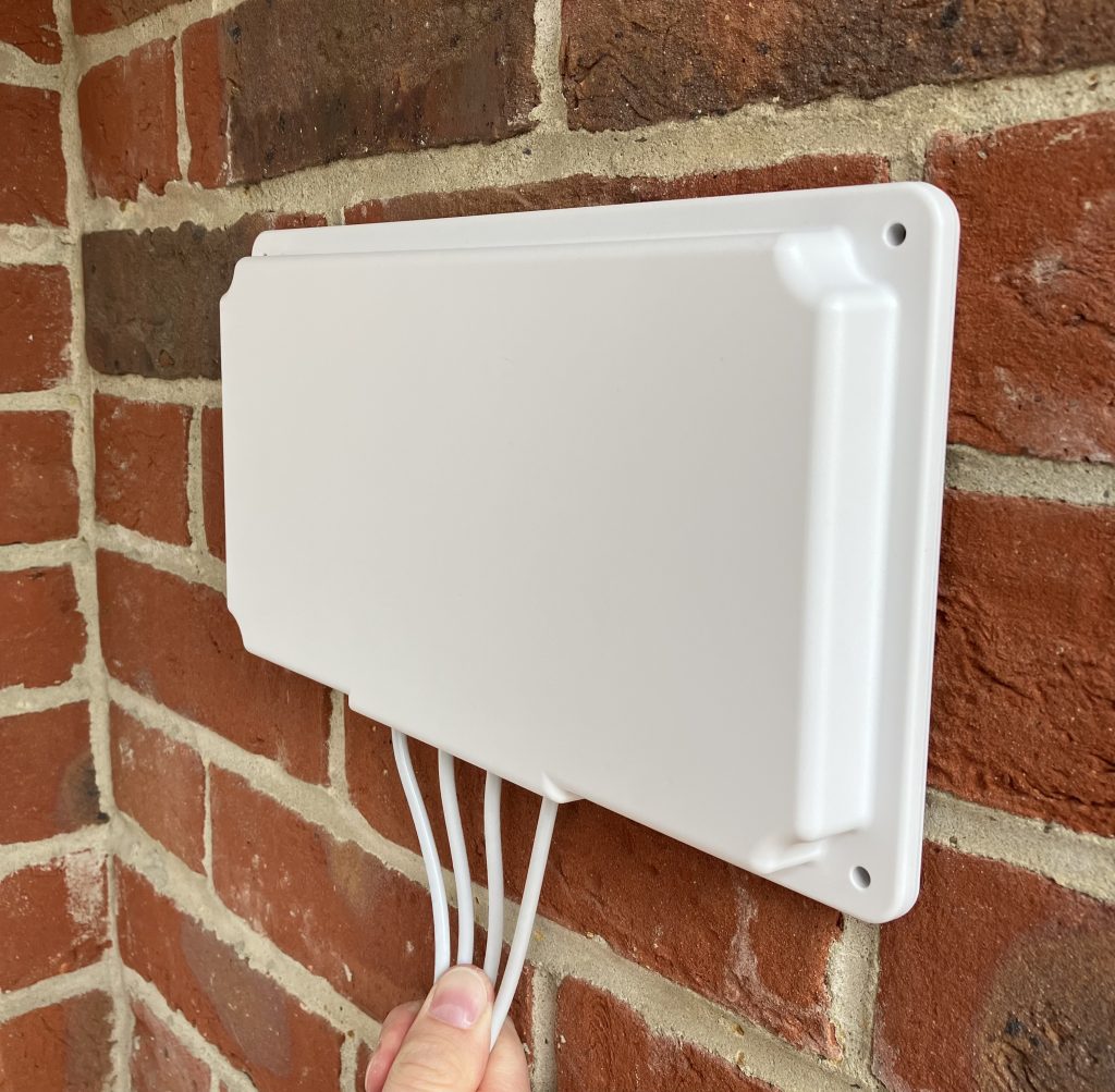
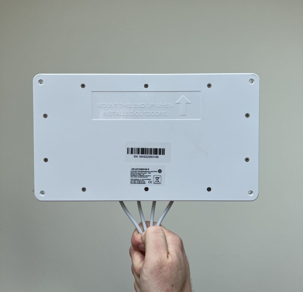
We are going to use use Cisco’s AIR-ANT2566P4W-R, which has a nicely squished pattern and changes to its orientation are very visual.
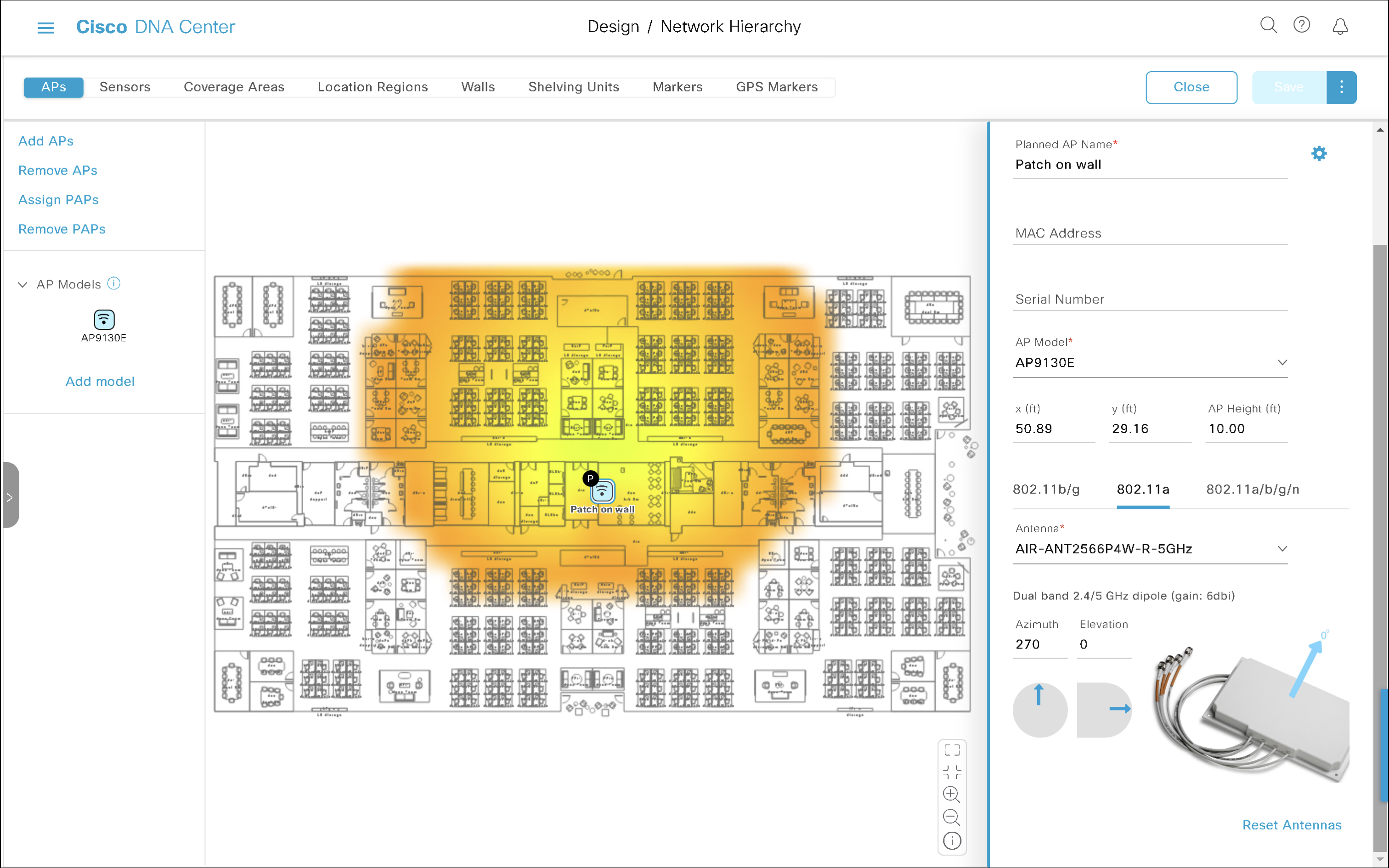
Wall-mounted external antenna
By default DNA Center sets APs with external antennas to Azimuth 0 and Elevation 0. Elevation 0 means that the antenna is wall-mounted (downtilt 0°) and its main lobe shoots parallel to horizon.
Let’s assume perfectly wall-mounted antennas with no downtilt at all in the examples below. That way we don’t need to touch the Elevation setting at all. All we need to do is to adjust the Azimuth angle depending on which wall the antenna is mounted on.
Wall-mounted antenna shooting towards the right
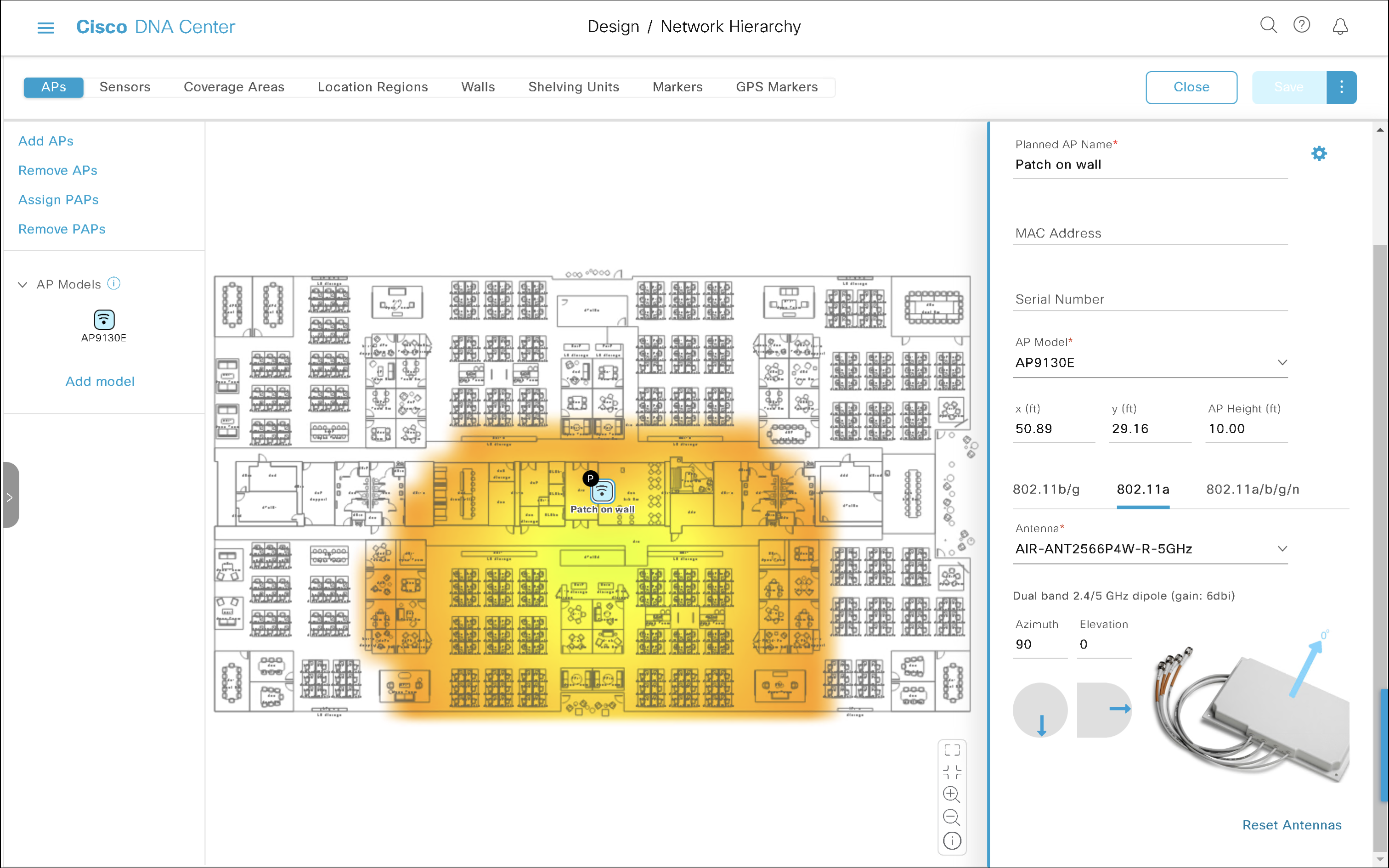
Azimuth 0 and Elevation 0 is the default setting for external antennas. It represents a perfectly wall-mounted antenna (that’s what Elevation 0 means) shooting in the right hand direction (that’s what Azimuth 0 does). The main lobe travels parallel to the floor.
Azimuth 0 and Elevation 0
On the floor plan, it is mounted on the ‘left wall’ of the room, shooting towards the right.
Wall-mounted antenna shooting towards the bottom of the map
Now, what if you installed the antenna on a wall, but it points towards the bottom of the map (I avoid the south as it is not true south) this time?
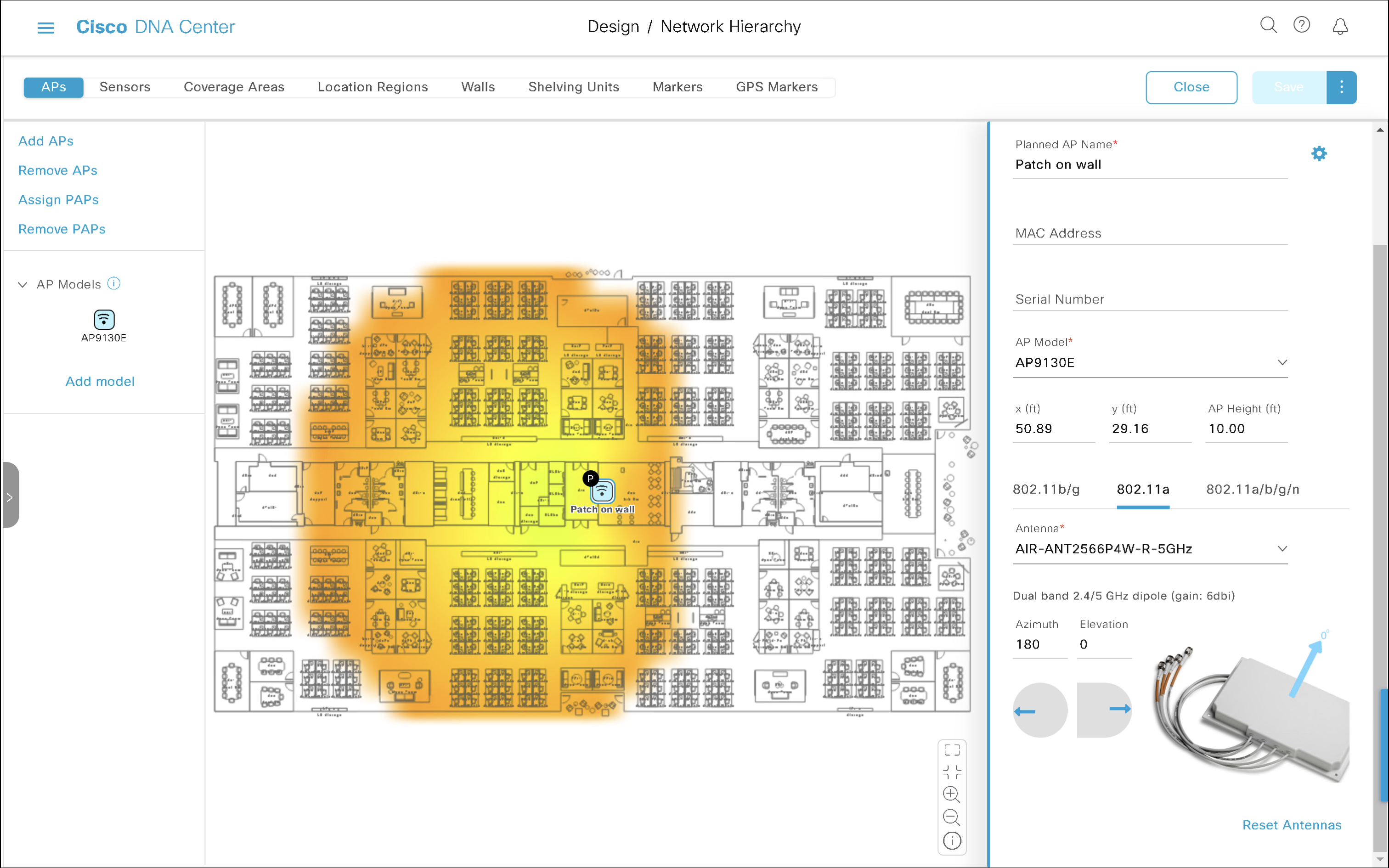
Azimuth 90 and Elevation 0
We rotated the antenna clockwise around it vertical axis by 90 degrees. There is Azimuth for that, so we will increase Azimuth by 90. The final setting is Azimuth 90 and Elevation 0.
The antenna appears as mounted on the ‘top wall’ of the room shooting towards the bottom of our floor plan.
Wall-mounted antenna shooting towards the left
We have now rotated the antenna by another 90 degrees clockwise. That results in Azimuth 180 and Elevation 0.
Azimuth 180 and Elevation 0
It is installed on the right wall pointed towards the left of our floor plan.
Wall-mounted antenna shooting towards the top of the map
Finally, if the antenna is mounted on the ‘bottom wall’ and it points towards the top of our floor plan, that is another 90-degree increment, and results in Azimuth 270 and Elevation 0.
Azimuth 270, Elevation 0
Hopefully, there are no surprises there?
If your antenna uses a different orientation, simply drag the blue Azimuth arrow and point it wherever the antenna’s main lobe is shooting towards.
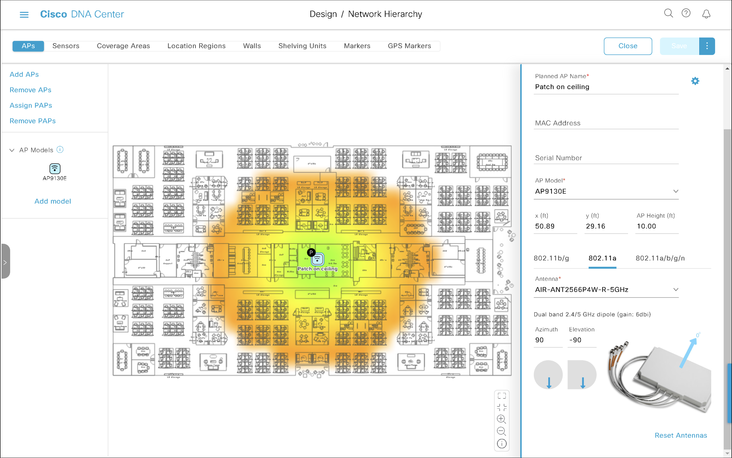
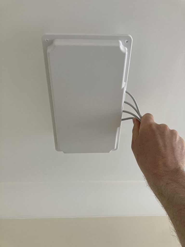
Ceiling-mounted antenna
Ceiling-mounted antenna shooting towards the floor
Antenna mounted to the ceiling shooting towards the floor has downtilt of 90°. We simply set Elevation to -90. Don’t miss the minus sign.
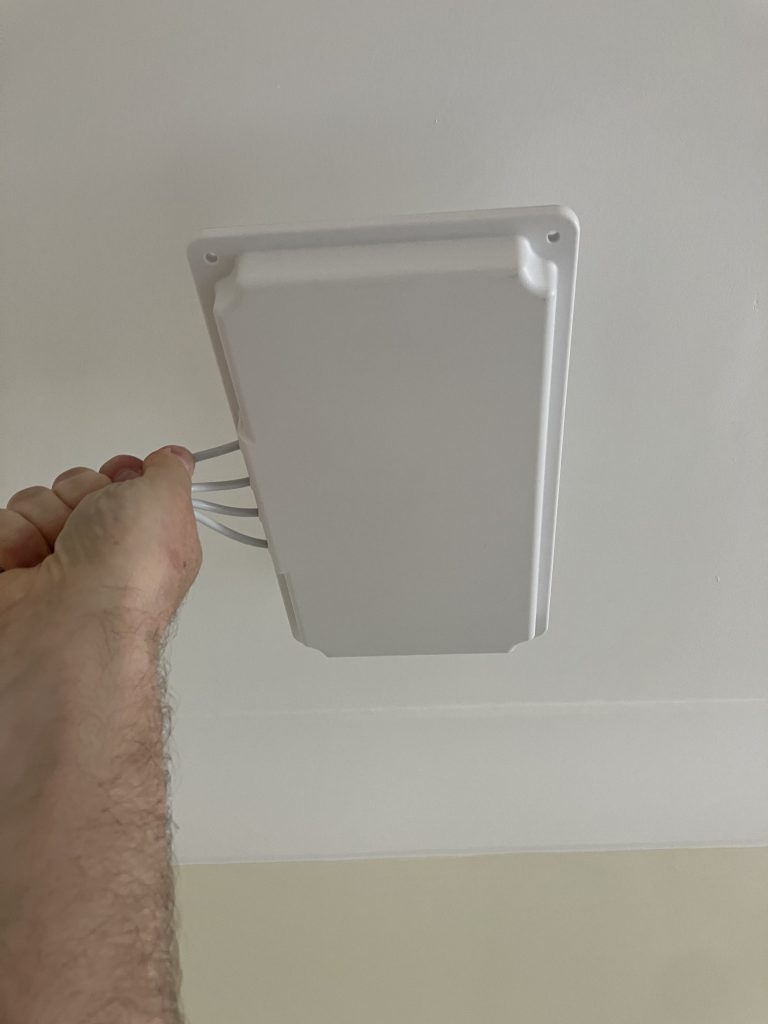
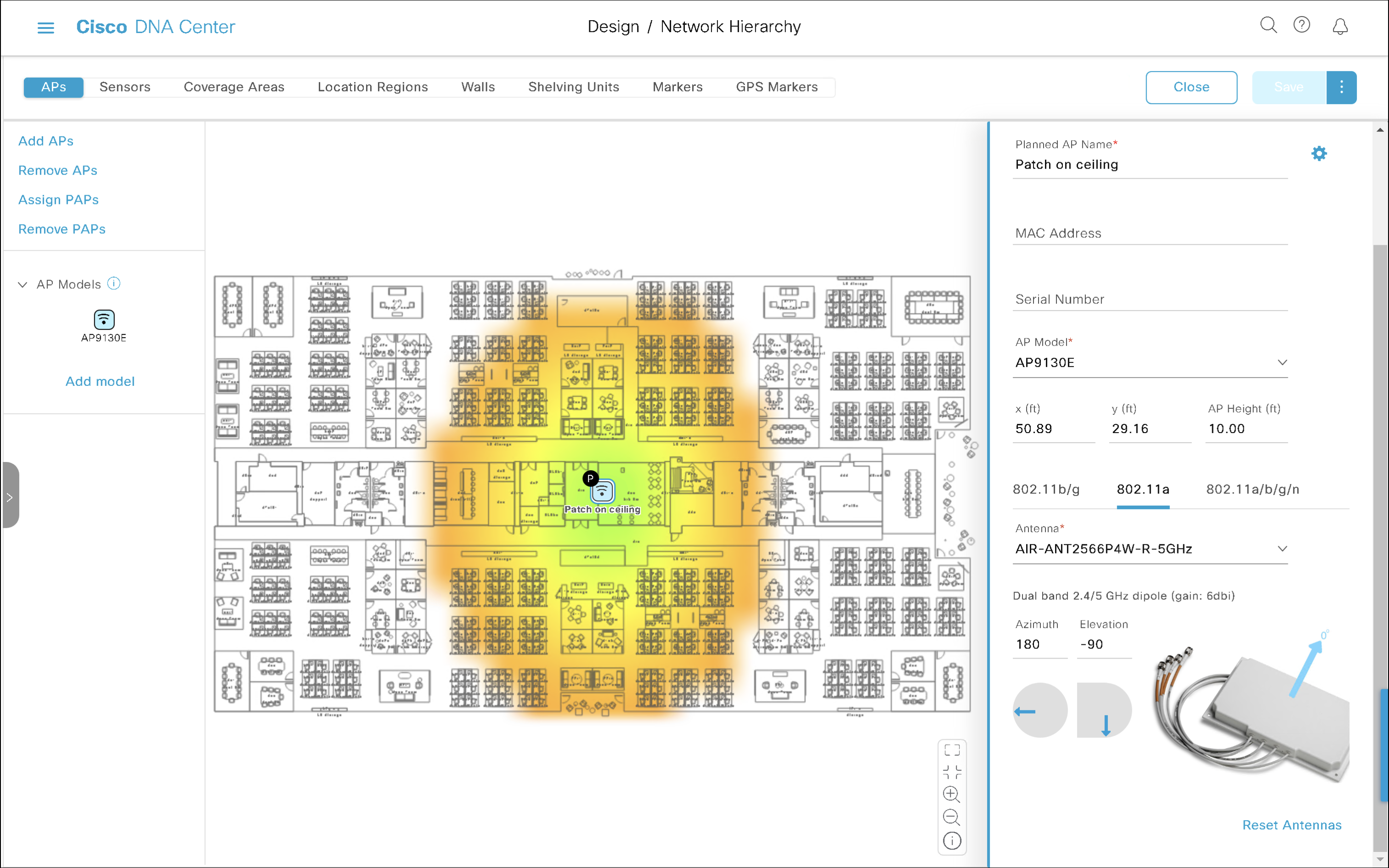
This is how Azimuth 0 (antenna cables on the left, top side of the antenna on the right) and Elevation -90 looks like.
Azimuth 0, Elevation -90
The irregular ‘oval-ish’ pattern of this patch antenna is very obvious on the map. It kisses the top and the bottom of the floor plan.
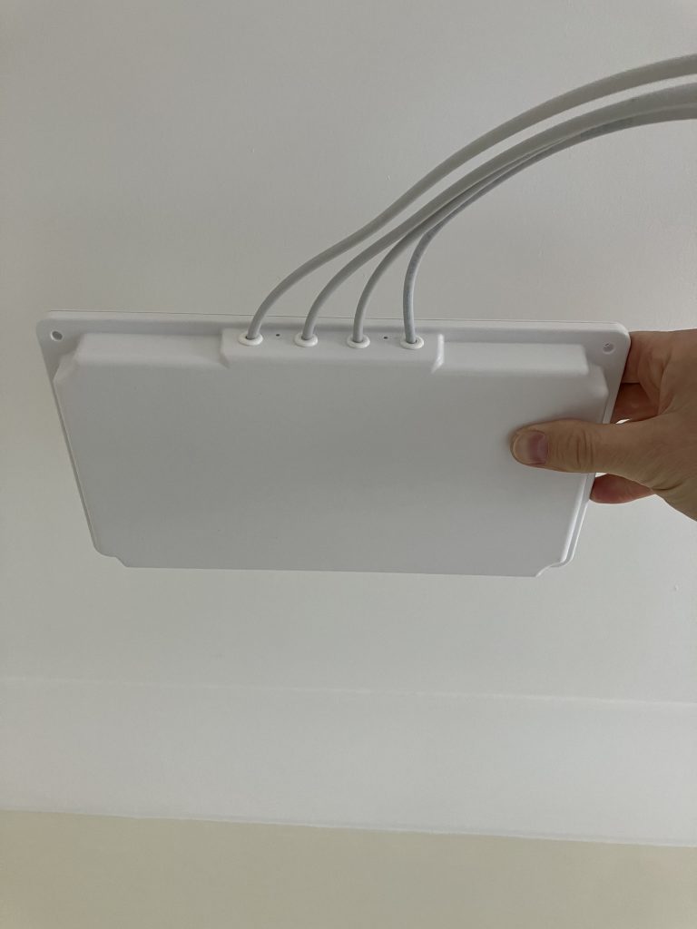
My antenna is ceiling-mounted but it is rotated?!
To rotate the antenna on the ceiling by 90° clockwise, we just need to increment Azimuth.
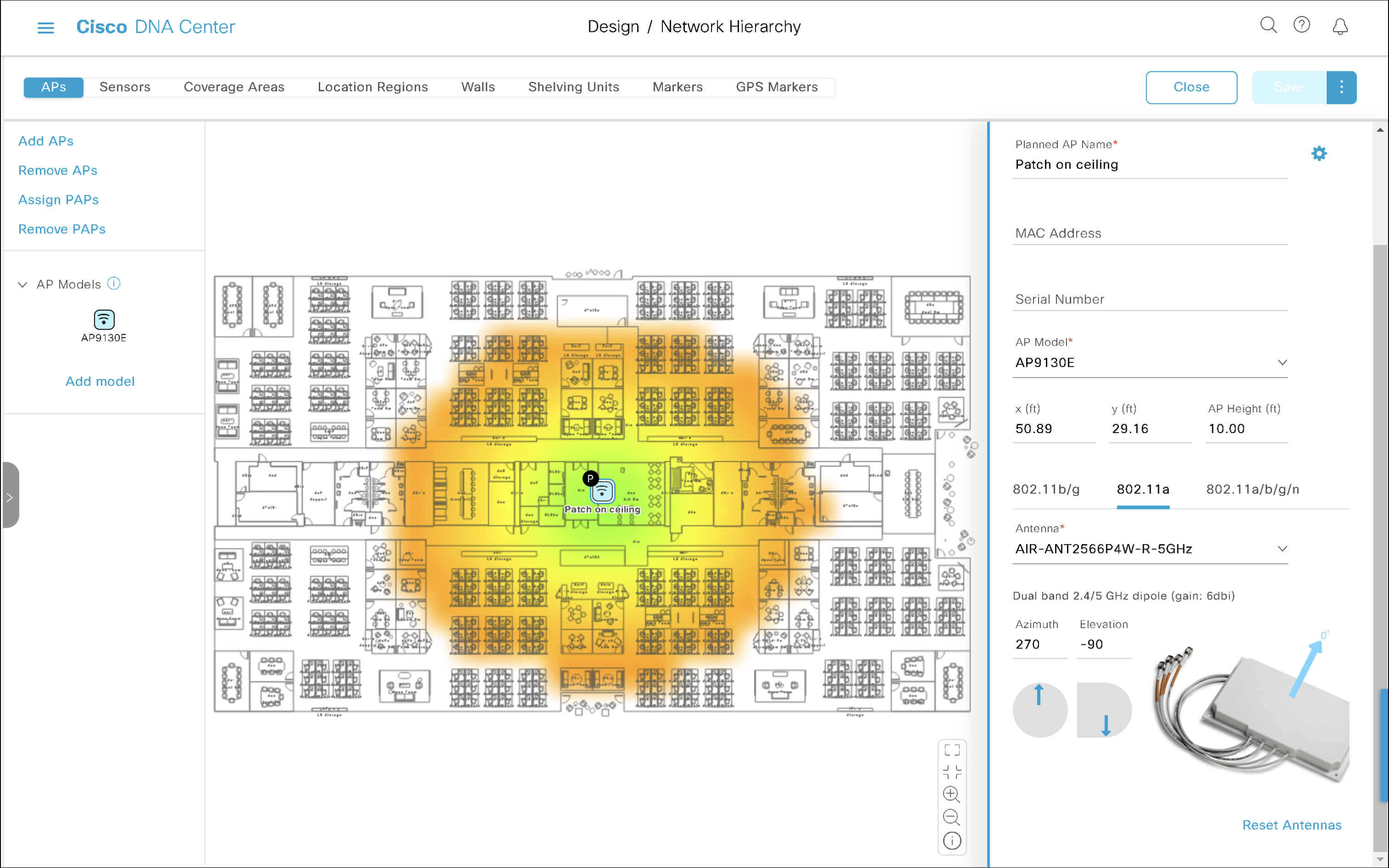
Azimuth 90, Elevation -90
Azimuth 90, Elevation -90
This time the coverage area stretches from left to right, because we rotated the antenna by 90 degrees.
Azimuth 180, Elevation -90
Azimuth 180, Elevation -90
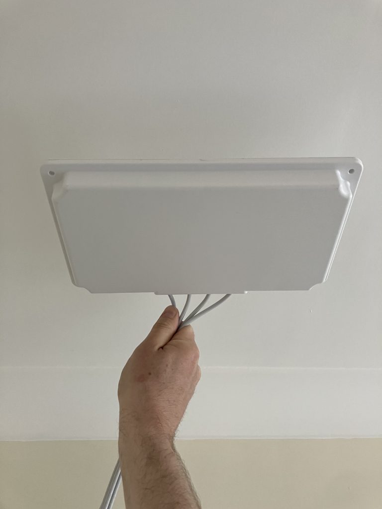
Azimuth 270, Elevation -90
Antenna cables point towards the bottom of the map, which is yet another 90-degree increment. It is still perfectly ceiling-mounted (that’s Elevation -90).
Azimuth 270, Elevation -90
Let’s practise
Now, let’s apply the theory.
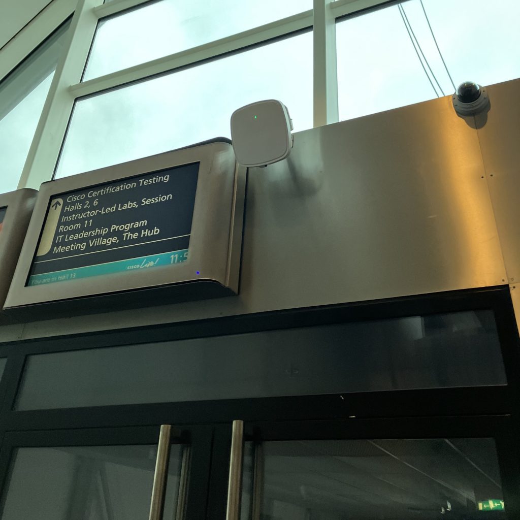
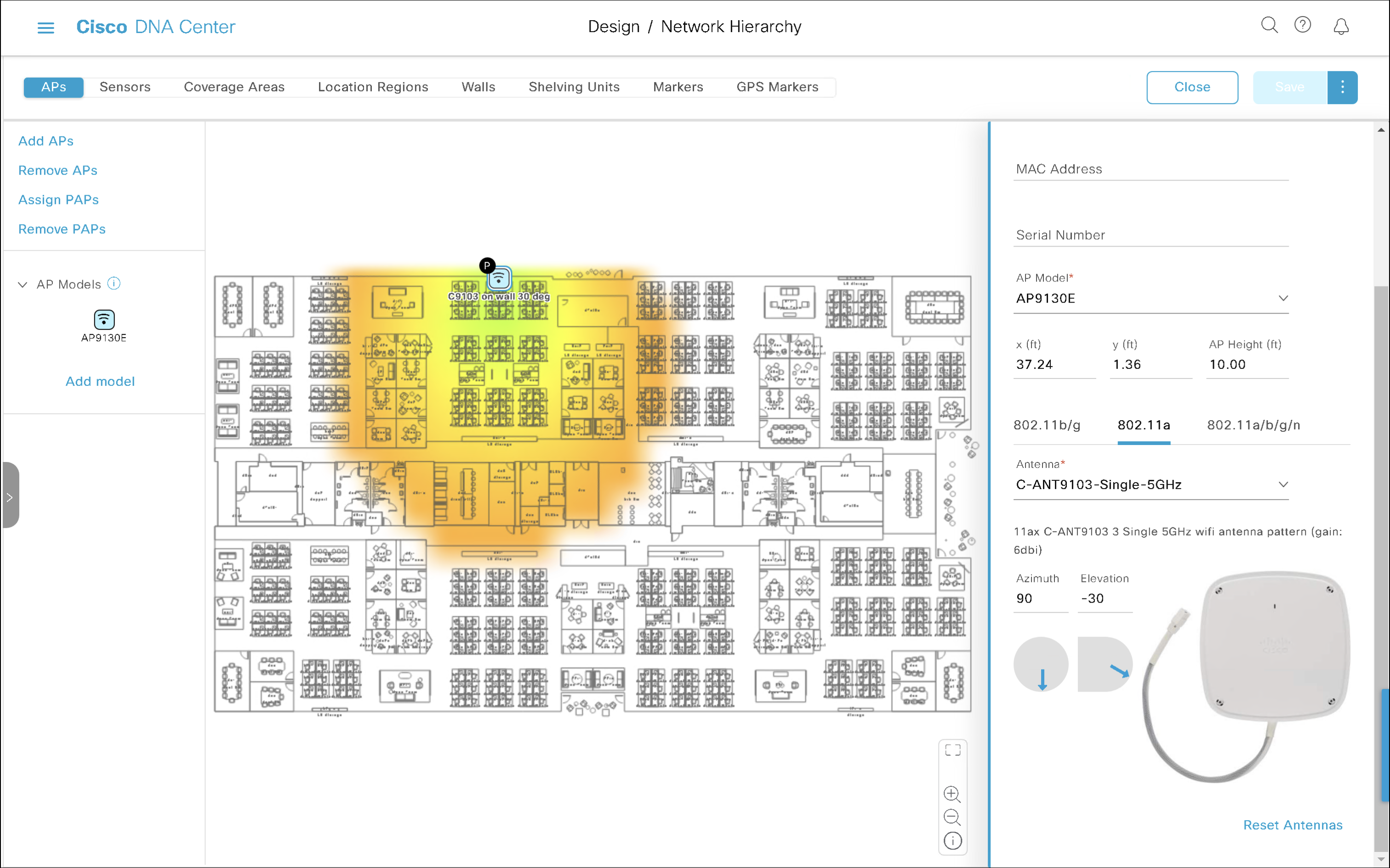
What Azimuth and Elevation would you configure on C-ANT9103 antenna connected to Catalyst 9130 AP mounted using AP-BRACKET-9 bracket on the ‘top wall’ (don’t let the perspective of the photo confuse you) of the floor plan with 30-degree downtilt?
Azimuth 90, Elevation -30
The antenna is mounted on the top wall shooting to the bottom of the map. That translates to Azimuth 90. It is wall-mounted, which normally means Elevation 0, but it is tilted 30° down. So, we subtract 30 from Elevation. And here we go, that’s Elevation -30.
Cisco Catalyst Wi-Fi 6E access points in DNA persona support a new Site Survey mode. It allows you to perform AP-on-a-stick survey, it comes with a fresh web interface, and it supports 6 GHz. This new mode is included in the Lightweight access point software image.
Unlike the Embedded Wireless Controller (EWC) mode, which was available on previous generation of APs, this new Site Survey mode doesn’t require any extra software image download or reflash of the AP.
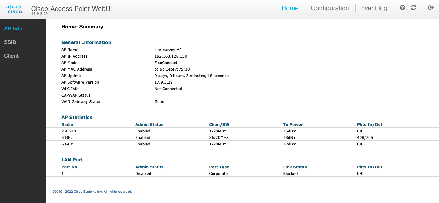
CW9162 access point in Site Survey mode
What do we need
Either of C9136I, CW9166I, CW9164I and CW9162I APs in DNA persona (controller-managed AP running Lightweight software image) works. We are going to use CW9162I-ROW DNA persona AP running 17.9.3 or newer release.
Console cable connected to the USB port of your laptop and the RJ45 Console port of the AP
PoE injector, PoE-capable battery pack, or switch with PoE support. To power CW916x APs, PoE+ (802.3af) is sufficient. You will need UPOE (802.3bt) to leverage full radio capability of C9136I.
Why the 17.9.3 or newer release
Why am I insisting on 17.9.3 or newer release? There was an issue, which prevented Site Survey mode from working on ROW regulatory domain APs used in the UK. The AP simply won’t accept the GB country code, and it won’t enable 5 GHz and 6 GHz radios. This is fixed in 17.9.3.
How to upgrade the AP to 17.9.3
Simply join the AP to an existing Catalyst 9800 controller running 17.9.3 release. During the join process, the AP will automatically upgrade its software to 17.9.3 to match your controller’s release.
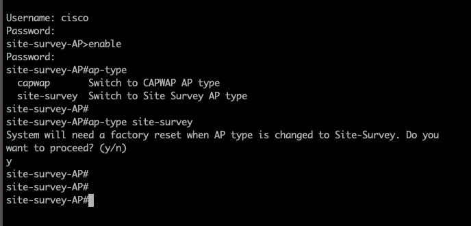
Console into the Lightweight AP. Please note Catalyst APs used 9600 baud rate by default, which has recently in 17.12.1 release changed to 115200 bauds.
Switch the AP to Site Survey mode using this command, press y, and wait for it to reload:
ap-type site-survey
Note: Mode change to Site Survey mode erases the AP settings and resets Console port credentials to cisco/Cisco.
After it reloads, ROW domain AP will only broadcast 2.4 GHz survey SSID. No 5 GHz. No 6 GHz. That’s because we haven’t configured any country code yet and it doesn’t know what regulatory to follow. Note the Country NONE value.
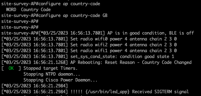
If you are using ROW (Rest Of World) domain AP, configure country code using this command using Console connection and reload:
configure ap country-code GB
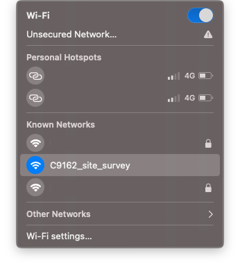
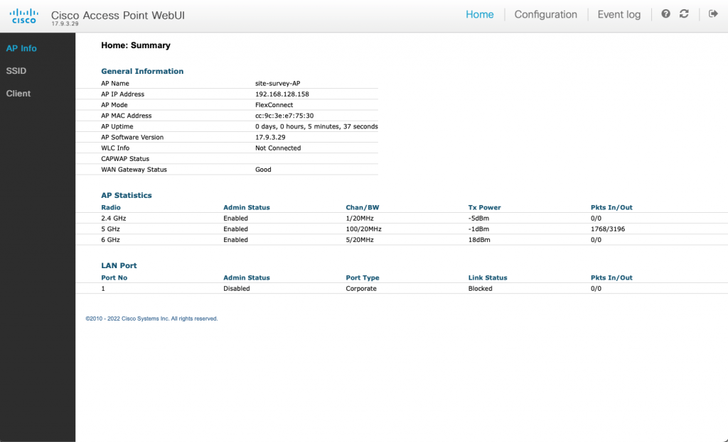
The AP will boot up and broadcast the survey SSID on all 3 bands.
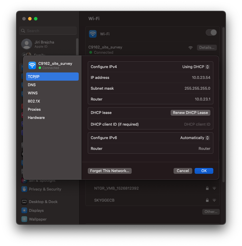
Connect to the survey SSID wirelessly. It is an open SSID, no passphrase needed.
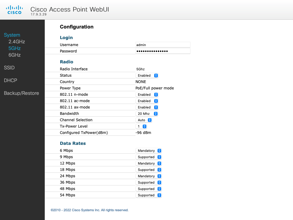
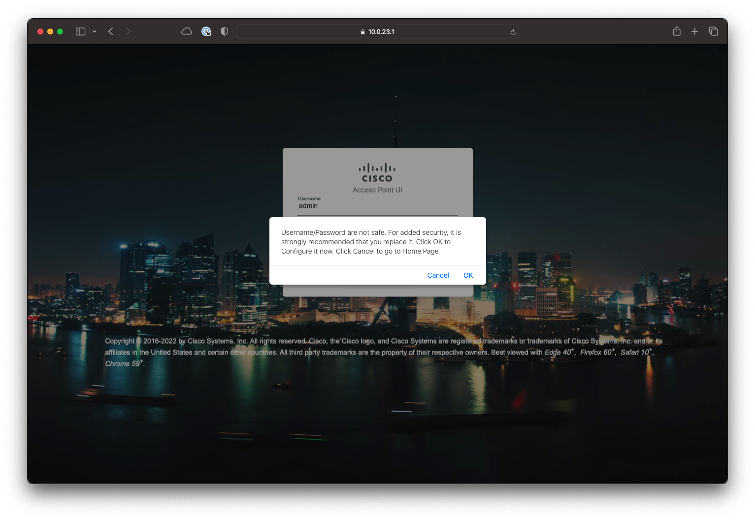
Access the access point’s web interface on https://10.0.23.1. Default credentials are admin/admin. Click OK, and change default credentials.
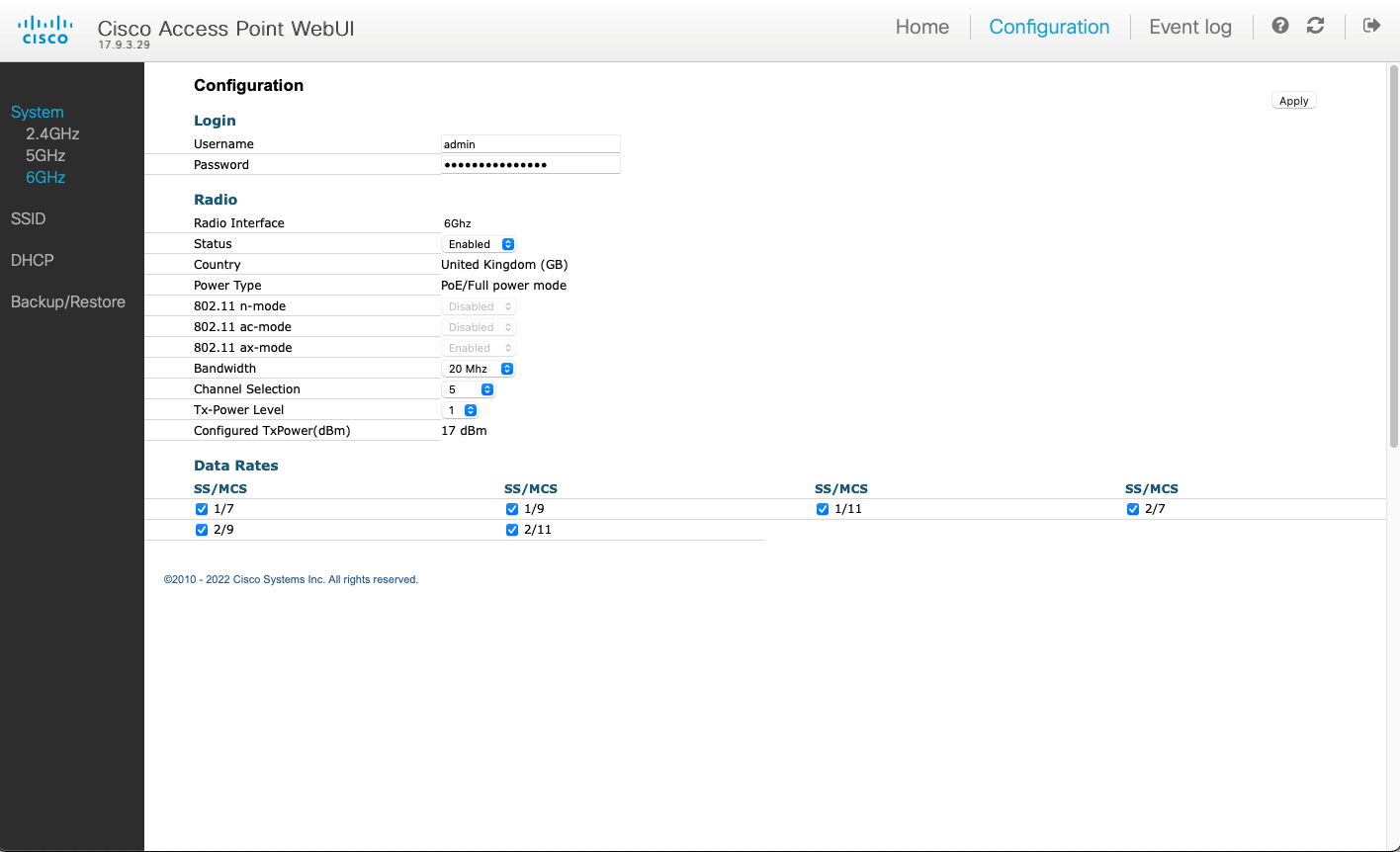
Using the web UI, customise the RF settings to fit your survey needs. Default 6 GHz channel setting is set to Auto, which results in channel 1, which is not a Preferred Scanning Channel (PSC).
Let’s change it to channel 5 or other PSC channel.
That’s it. Take the AP with you to site and enjoy the survey. When you PoE power it, it will automatically start in the Site Survey mode with your customised settings.
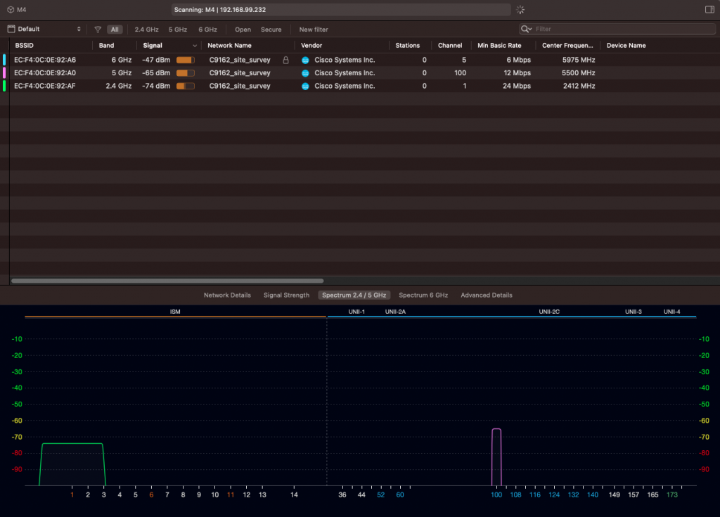
To scan 6 GHz spectrum, I use WiFi Explorer Pro with WLAN Pi M4 as a remote sensor. It has a built-in tri-band Wi-Fi adapter.
Custom 6 GHz channel and Tx powerSite survey SSID enabled on all 3 bands
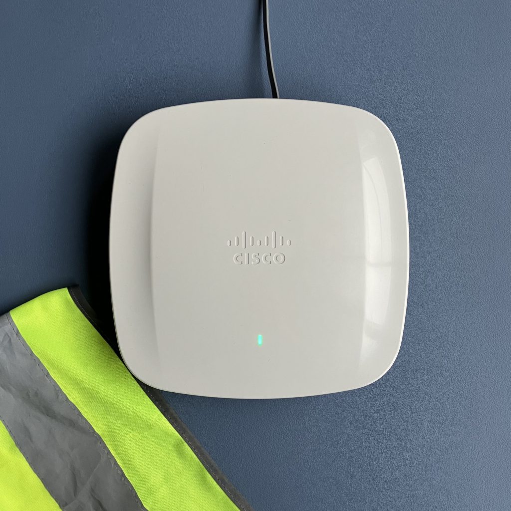
New LED pattern in Site Survey mode
During boot, the LED flashes blue.
After the AP successfully starts Site Survey mode, the LED flashes red and green. This is a normal Site Survey mode pattern, and absolutely nothing to worry about.
LED flashes red and green in Site Survey mode
Warning: Read before you switch back to CAPWAP mode
Take a deep breath before you do this
If you switch the AP from Site Survey mode back to CAPWAP mode, you will no longer be able to log in via its Console port. The mode change wipes all CAPWAP settings of the AP including credentials. If you proceed with switch to CAPWAP mode, you will have to perform these steps to regain Console port access:
Join the AP to a Catalyst 9800 controller
Create Console port credentials and Enable password in AP Join Profile of the controller (Configuration > AP Join)
Controller automatically pushes these newly created credentials to the AP
You can now login to the Console port of the AP and switch back to Site Survey mode or run other commands
How long does a Site Survey AP take to boot?
From plugging the Ethernet cable in to seeing the SSIDs on the air, it takes about 3-4 minutes. DFS channels take 4 minutes or so, other bands come up faster.
Does the AP need wired connectivity or IP address on its Ethernet interface?
No, wired connectivity is not needed. The AP can just be powered by a power injector with no upstream Ethernet link. No IP address is needed on the wired port of the AP.
Does internet connectivity work?
Yes, it does. If you connect AP’s Ethernet port to infrastructure that provides internet, wireless clients connected to the AP in Site Survey mode get internet access too.
The Ethernet interface of the AP gets an IP address via DHCP from the existing infrastructure. The AP has its own DHCP scope 10.0.23.0/24 enabled on its survey SSID. It then NATs traffic coming from wireless clients to the wired network.
This question comes up and every now and then. So, let’s put it to bed.
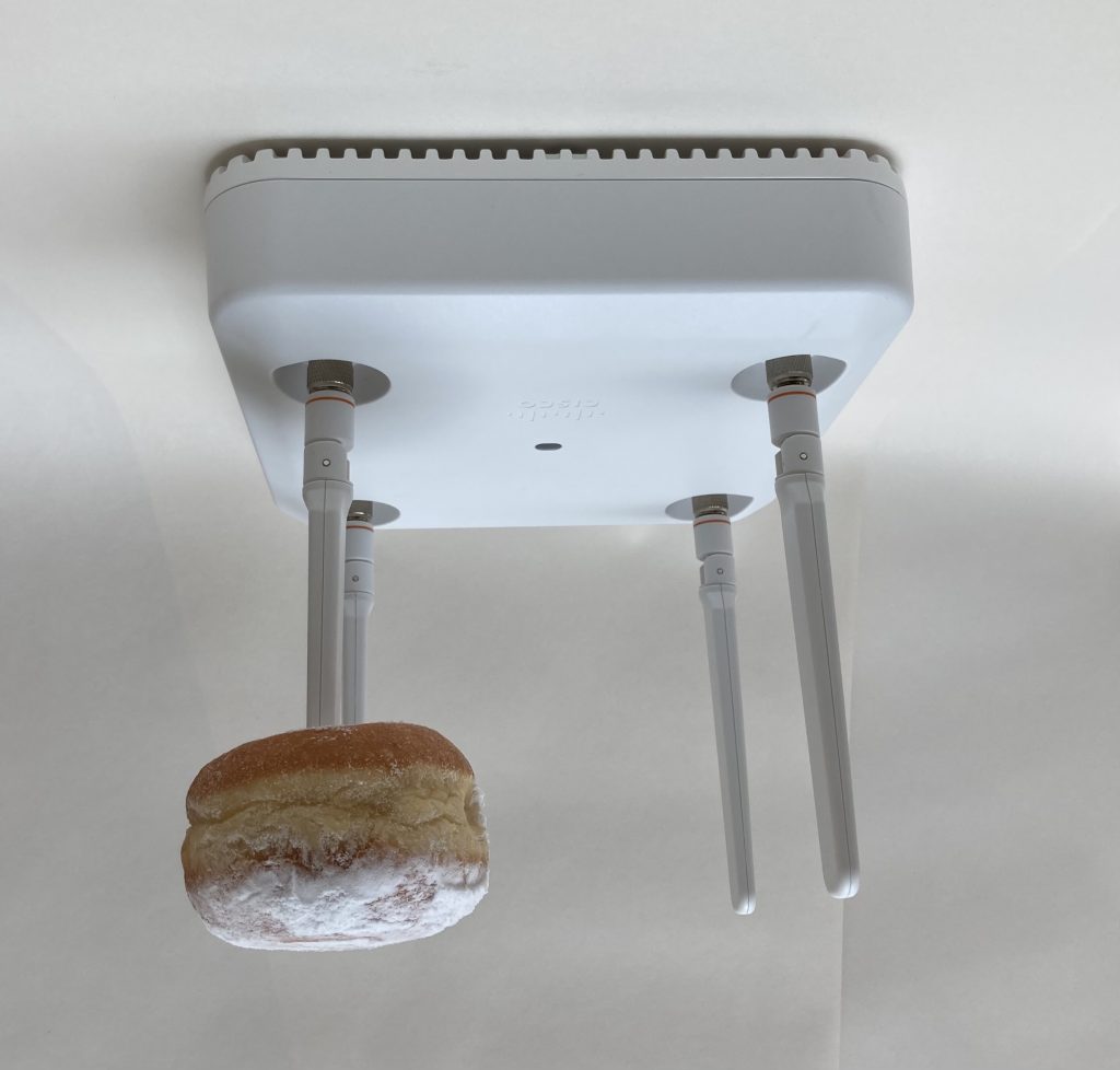
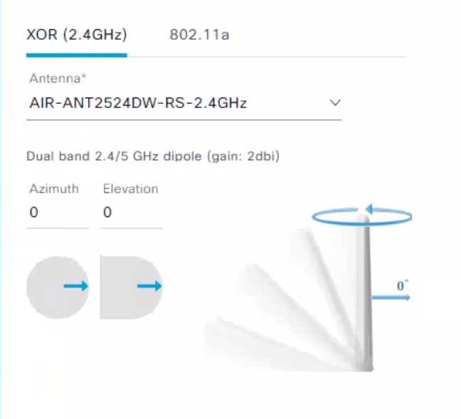
If you have a ceiling-mounted internal antenna AP (with built-in antennas), or external antenna AP with dipole antennas (AIR-ANT2524D), or with short dipole antennas (AIR-ANT2535SD), here are the correct Azimuth and Elevation angle settings.
This is how 0° Azimuth and 0° Elevation look like. Plus “squished doughnut” as a bonus to illustrate the coverage pattern 🍩
Azimuth angle does not matter in this case (it does for directional antennas), because these antennas have the same pattern regardless of how you rotate them clockwise or counterclockwise. Simply use the default value of 0°.
Elevation angle is 0° for this orientation.
Cisco DNA Center Azimuth and Elevation configuration
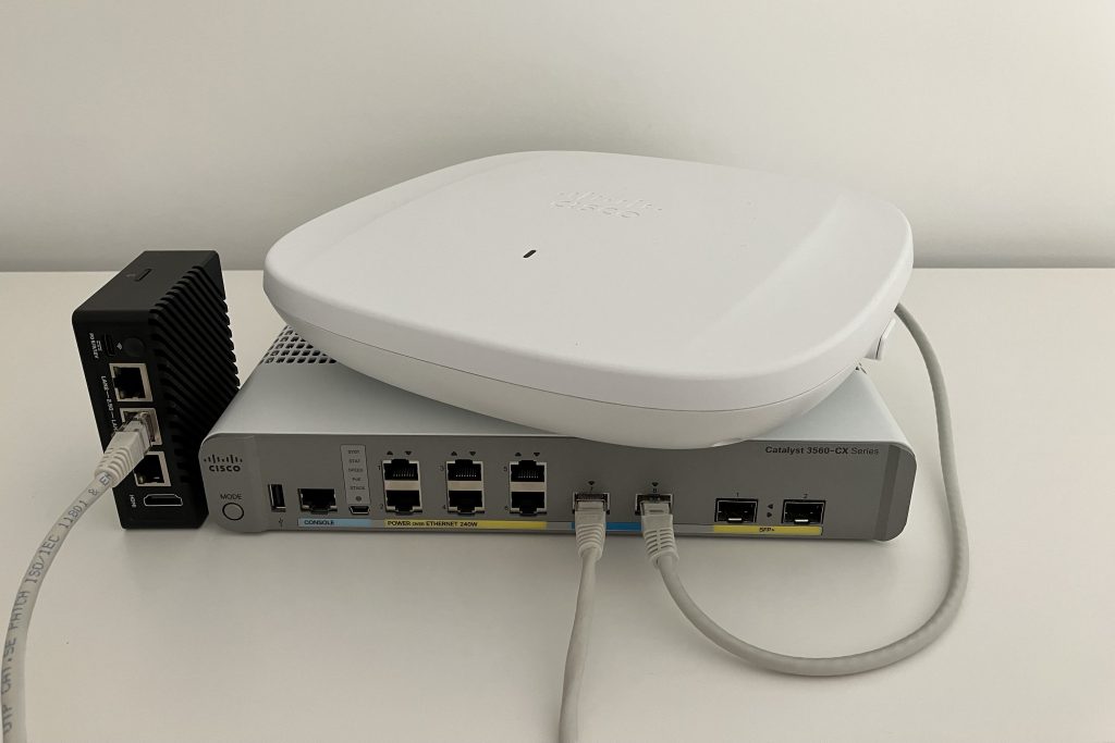
My Catalyst 9800-CL controller is hosted on a cloud, so I don’t need any hardware for that. Finally, my Catalyst 9136 Wi-Fi 6E AP is powered by a Catalyst 3560CX 10 Gigabit Ethernet multigigabit switch.
6 GHz 2×2 MIMO setup powered by PoE+
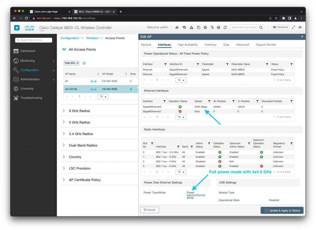
Catalyst 9136 is Cisco’s premium AP with all the bells and whistles including hexa-radio architecture and built-in environmental sensors for smart building use cases. It requires an 802.3bt/UPOE power source to enable 6 GHz radio in full performance 4×4 MIMO mode. The switch I use supports 802.3at/PoE+, which is great, but 6 GHz radio downshifts to 2×2. And that’s where an 802.3bt power injector comes to the rescue.
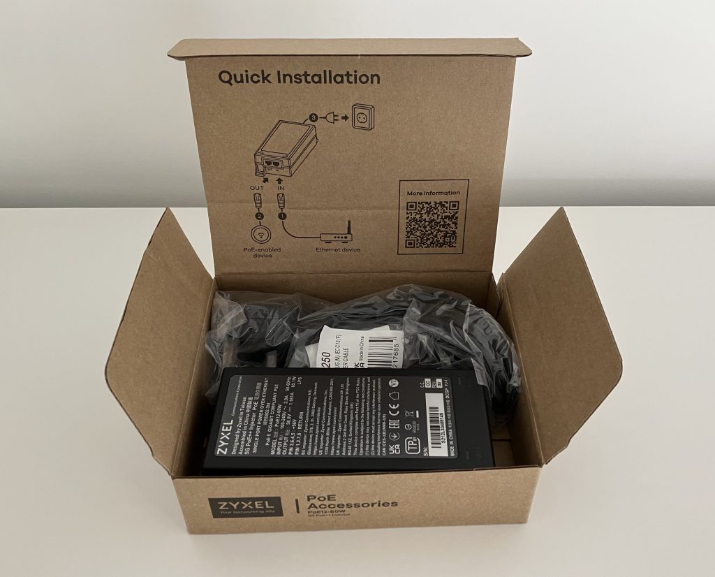
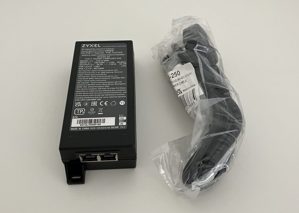
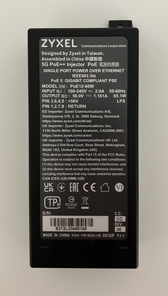
Since the Cisco injector isn’t widely available yet, I decided to test this Zyxel one. It provides 802.3bt power and allows the AP to run in full power and full 4×4 6 GHz radio mode with no compromise.
Do I like power injectors in production?
Absolutely not! Ideally you should design for 802.3bt/UPOE switches to power all your new APs via PoE.
It allows you to:
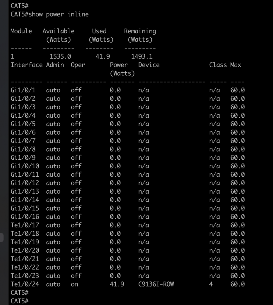
easily, centrally and remotely monitor how much power the APs use
enable/disable power on a port to bounce an AP
leverage redundant Platinum-rated power supplies for the AC to DC power conversion
manage the solution with ease – just think how difficult it is to manage more than 1 power injector, the number of AC power sockets, and what happens when someone disconnects the injector?
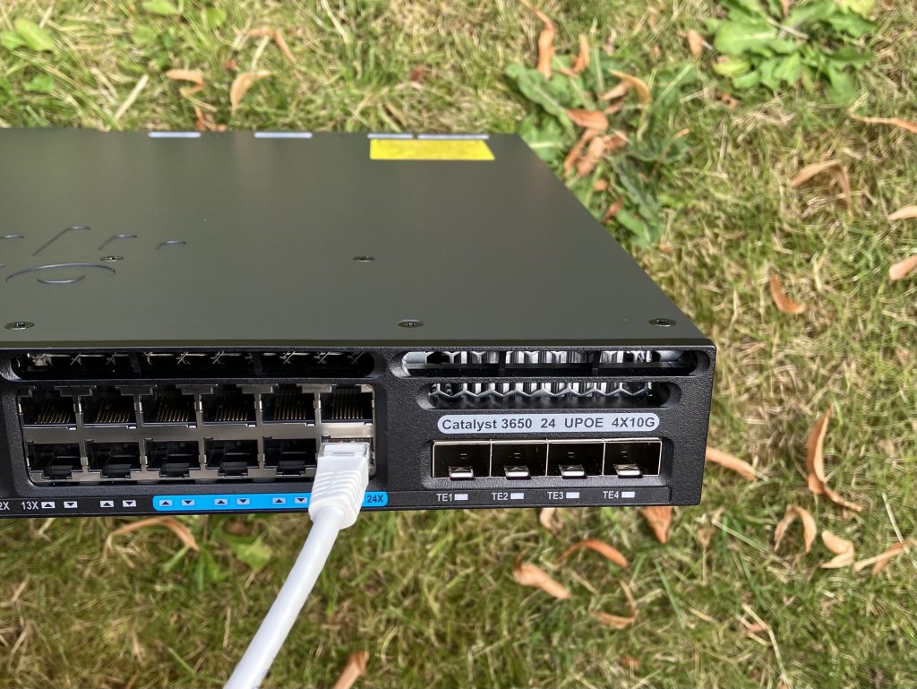
I still use C3650 UPOE mGig switch in my lab. Catalysts 9300 and 9400 the best choice these days.UPOE and mGig capable C3650 providing full power to the AP
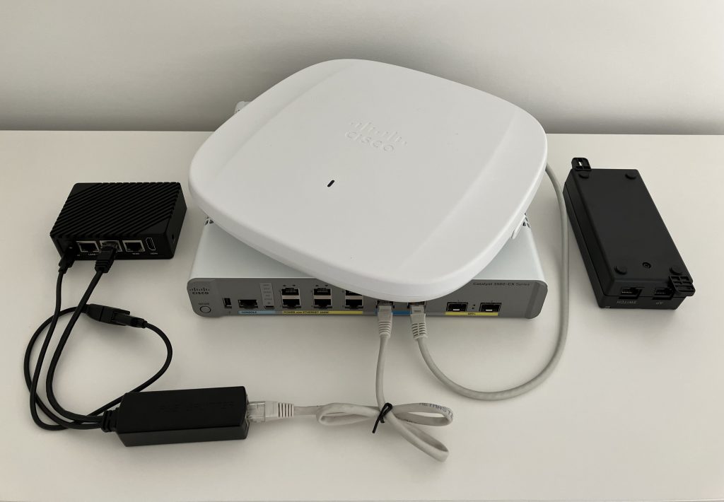
Final look
Carrying a full-size switch is not really an option for me, because small form factor is my main goal. So a power injector works best for me. But if I could I would love to use a compact 802.3bt switch.
Are you wondering if the PoE splitter connected to my iperf3 server (the little black box with 3 Ethernet interfaces) actually negotiated 2.5 Gbps Full duplex with the switch? Yes, it did. But keep in mind that the PoE splitter is technically only rated for 1 GbE. So use as short patch cable as possible and ideally CAT6.
Still few things to tidy up and perhaps I could build this into a nice Pelican case