One step closer to 10 Gigabit Ethernet on Raspberry Pi 5 – it is hot

This journey started as an exploration of maximum PCIe capabilities of Raspberry Pi 5 (and hopefully Compute Module 5) platform. I am mainly interested in multi-gigabit Ethernet and Wi-Fi 7 adapters connected via the PCI Express (PCIe) x1 bus.

Last time, we got throughput of 3.44 Gbps. The adapter and the Pi hit the bottleneck of PCIe Gen 2. Unfortunately, they failed to establish PCIe Gen 3 mode.

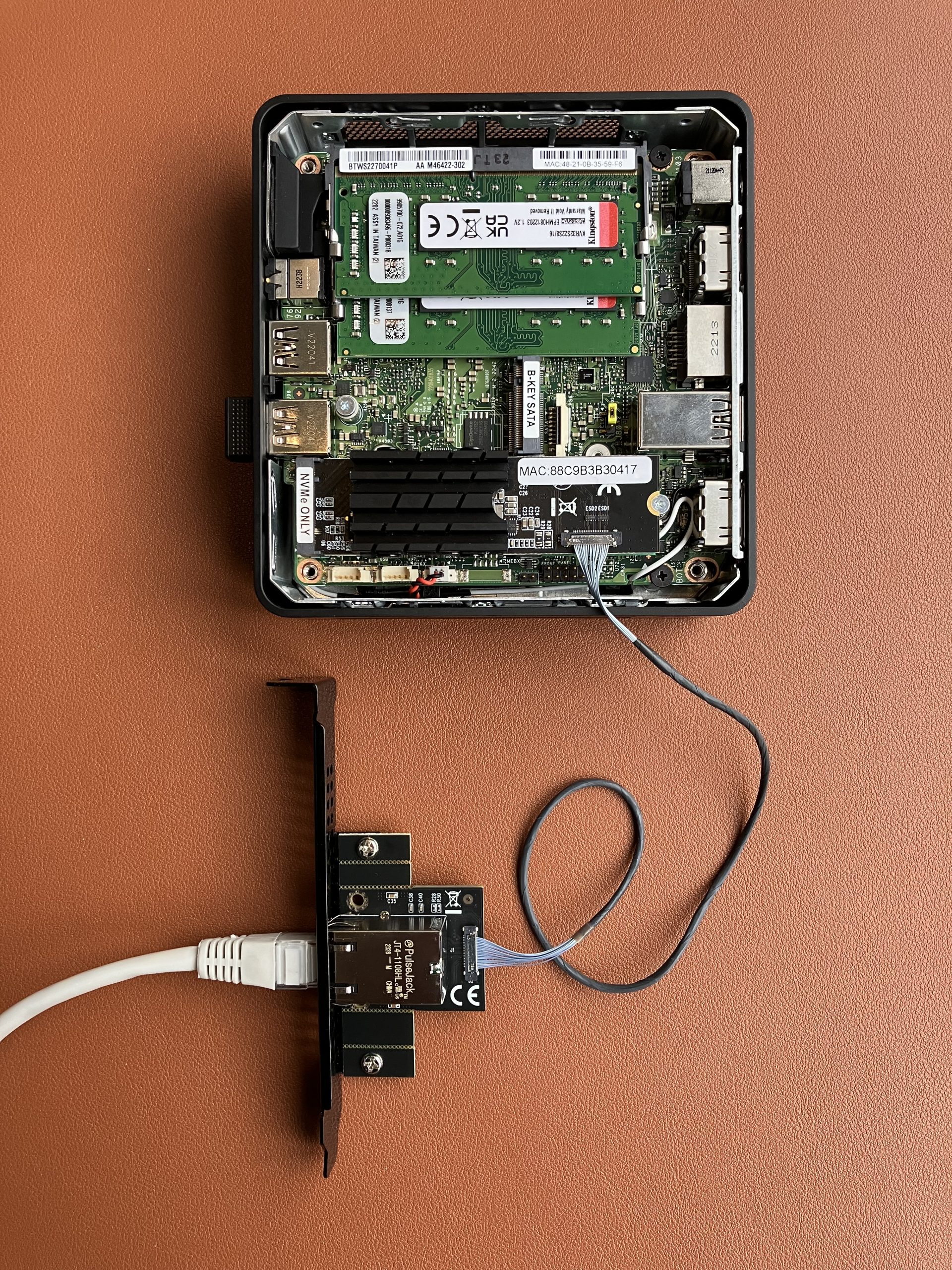
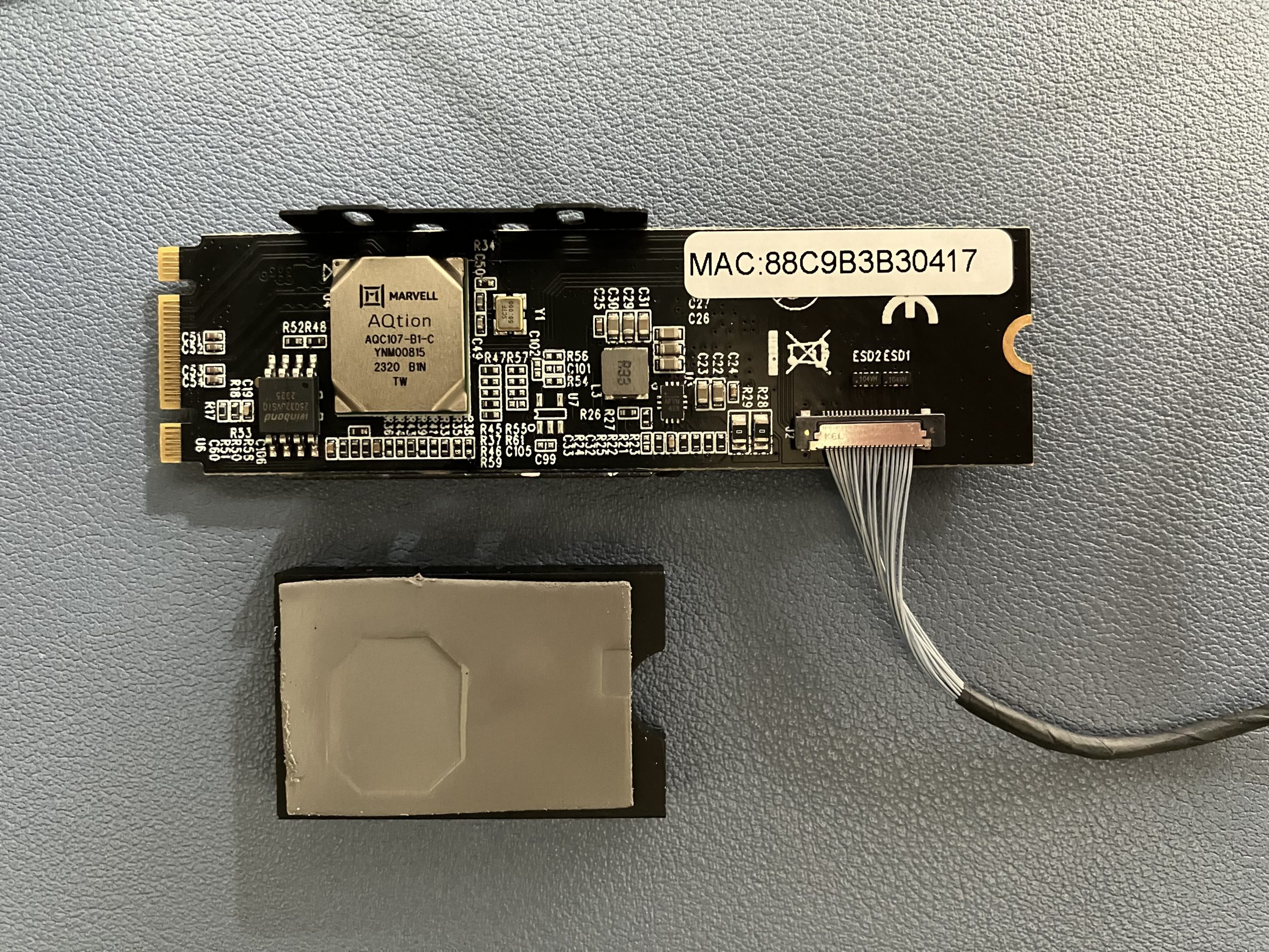
Generic 10 GbE adapter in M.2 form factor

This time we are going to use a slightly different adapter. It is available from various sellers under different names, but they all look and work the same. I picked up one from “KALEA-INFORMATIQUE” which happened to be readily available in the UK.

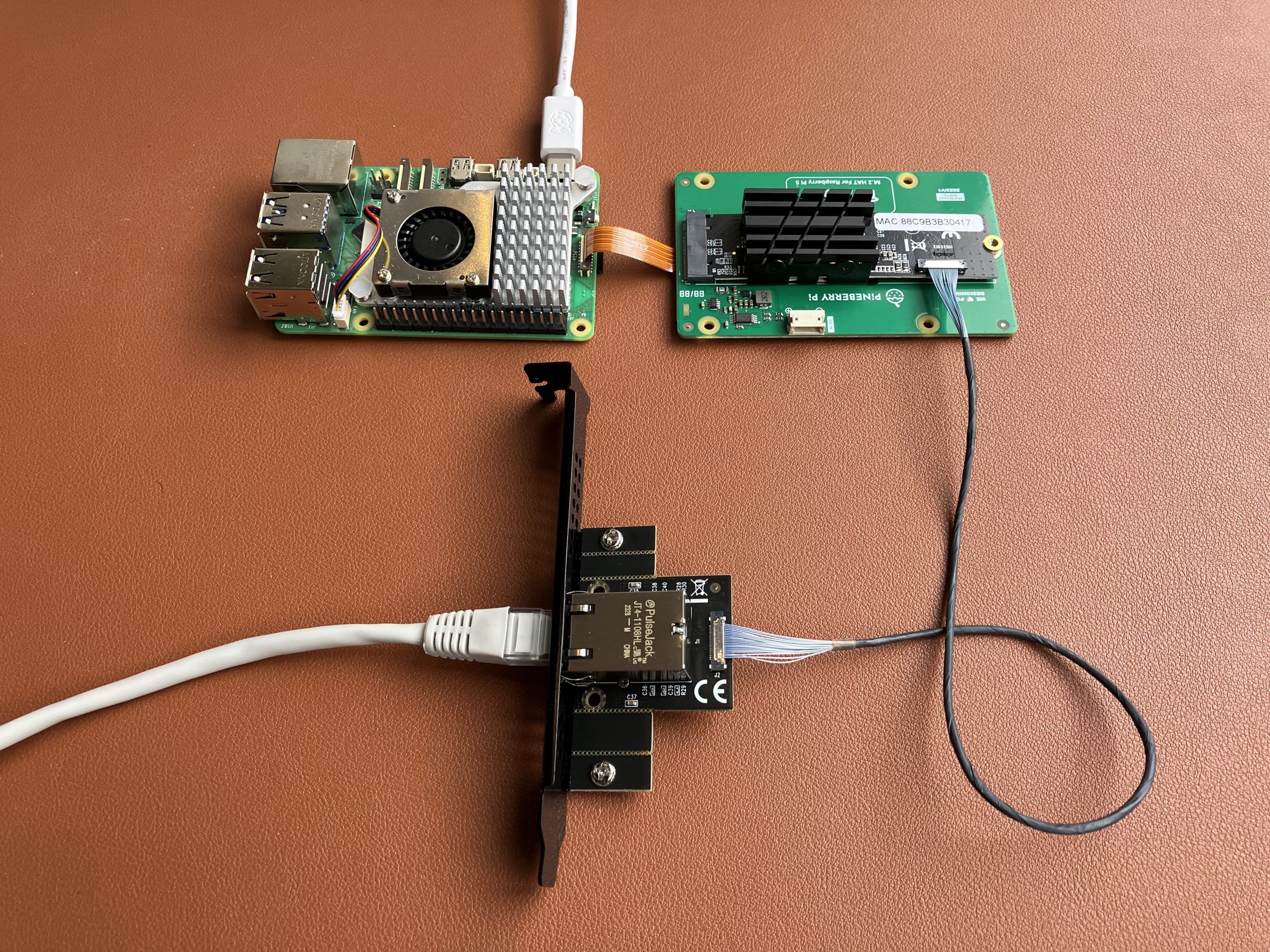
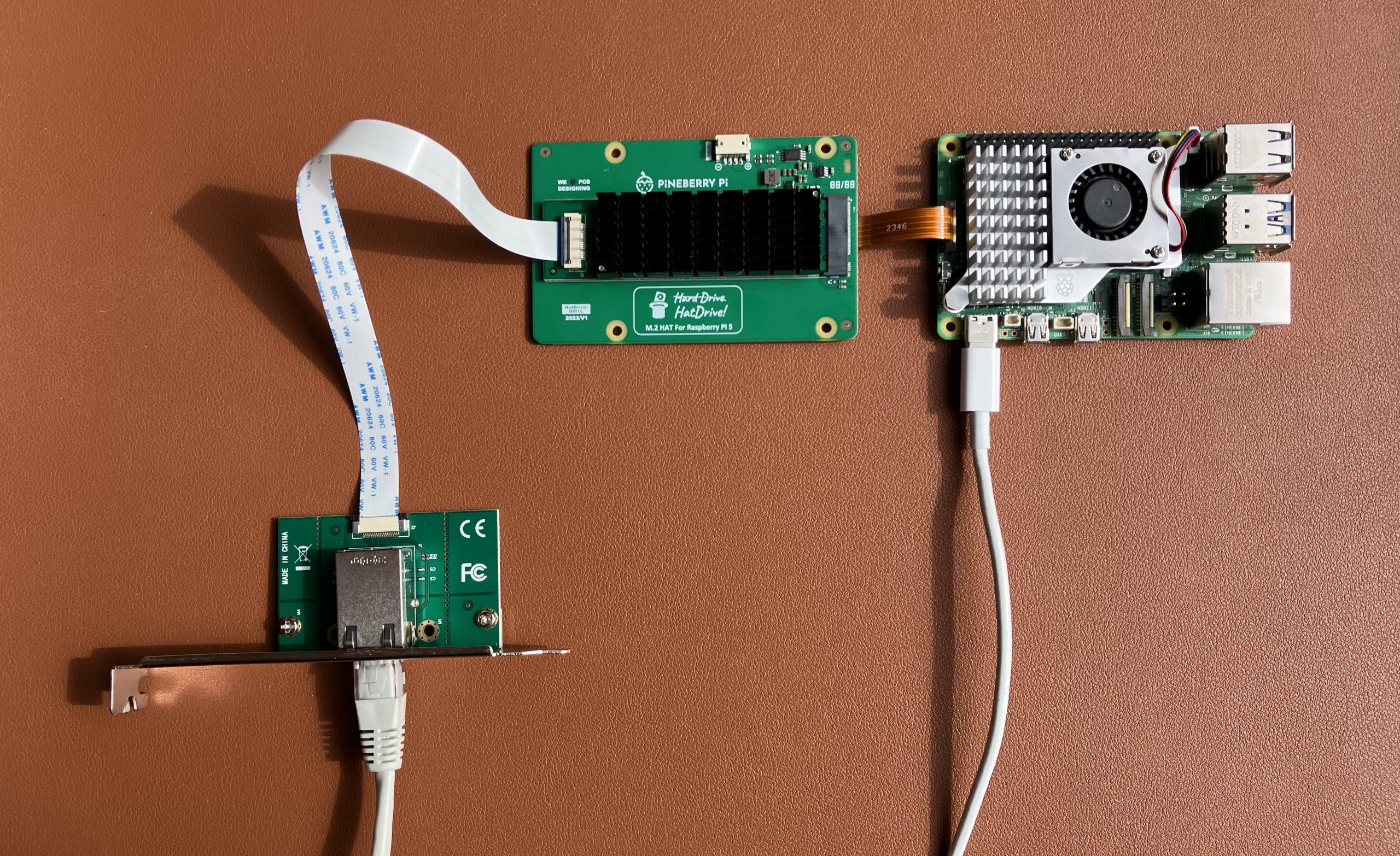
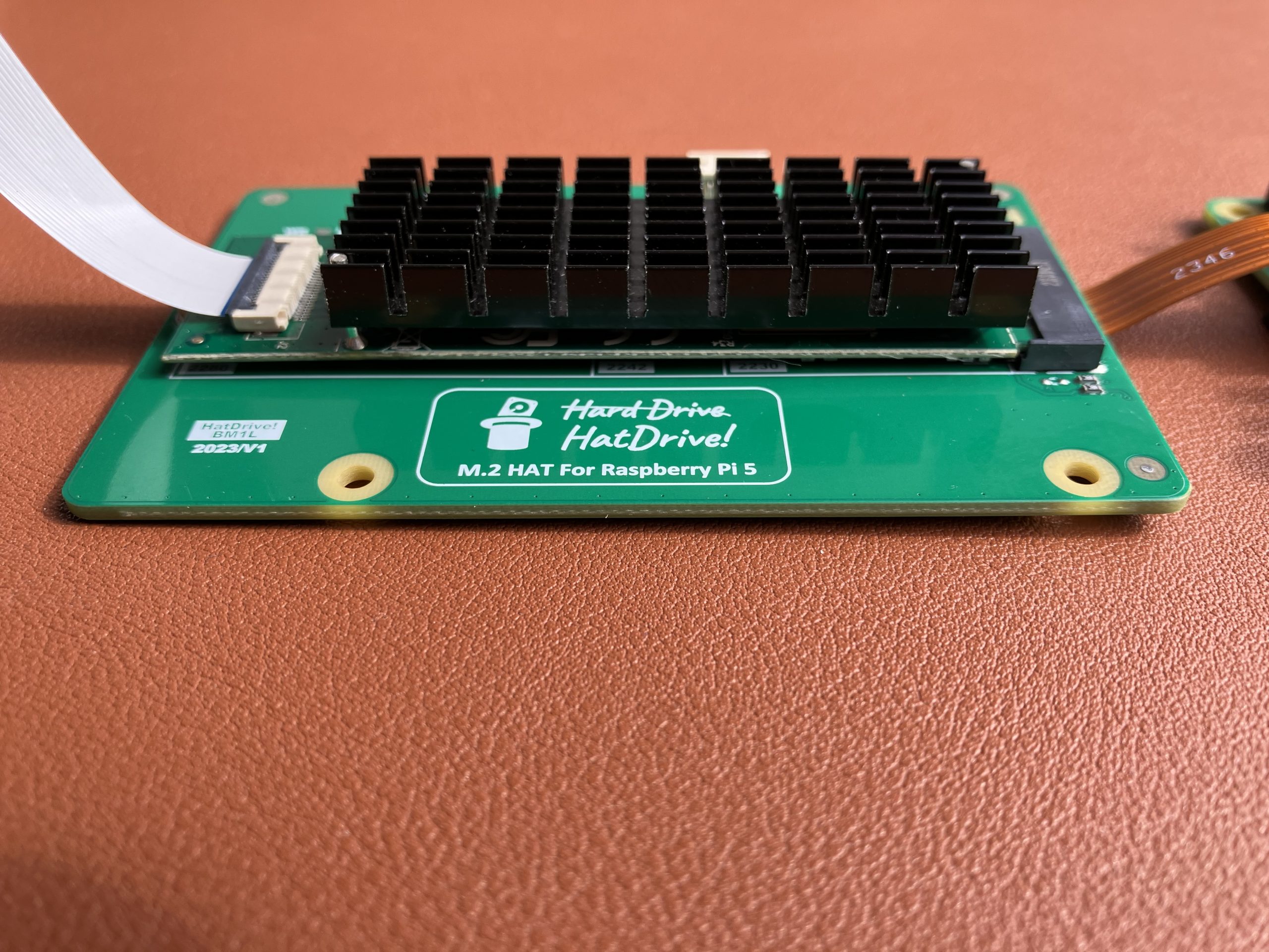
Pineberry’s HatDrive! Bottom breaks out Raspberry Pi’s PCIe connection to M.2 M-key format, and that’s where this 10 Gigabit Ethernet adapter plugs into.

Raspberry Pi 5 with 10 GbE adapter

Detail of the Ethernet adapter

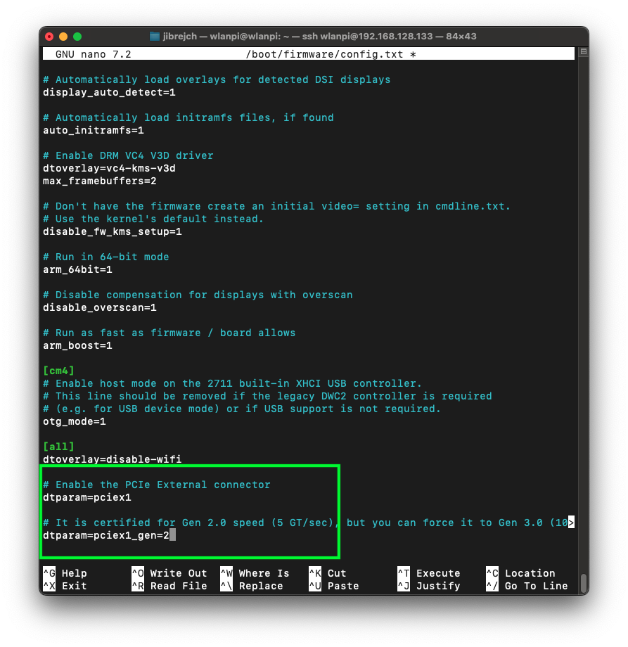
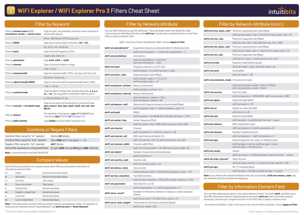
Build custom kernel with AQC107 support

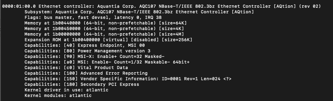
This Ethernet adapter uses the same chip and driver the one we previously tested. Here are the steps to make compile a custom Linux kernel that supports the adapter.

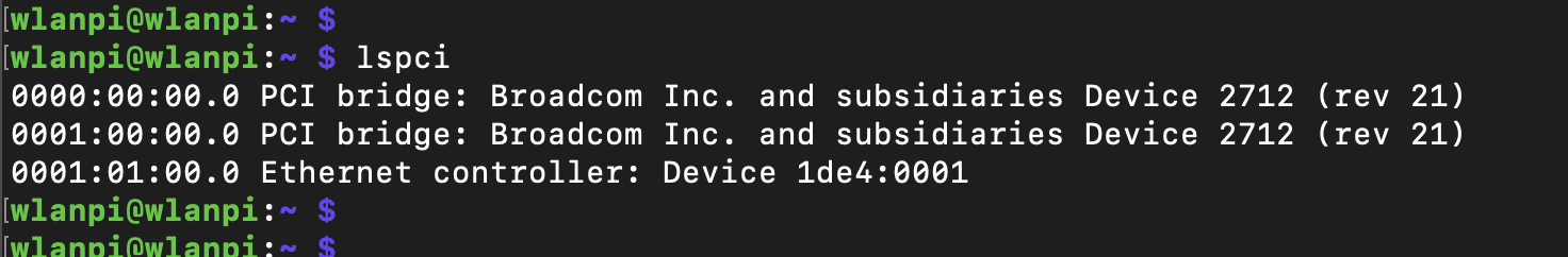
Wait, why is it still not working?

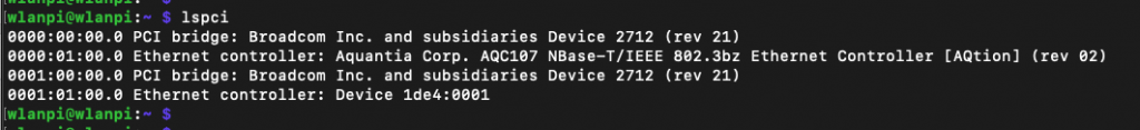
We have connected everything, built a custom kernel, we can see the device, but the Ethernet interface is not coming up.

lspci
lspci -v output

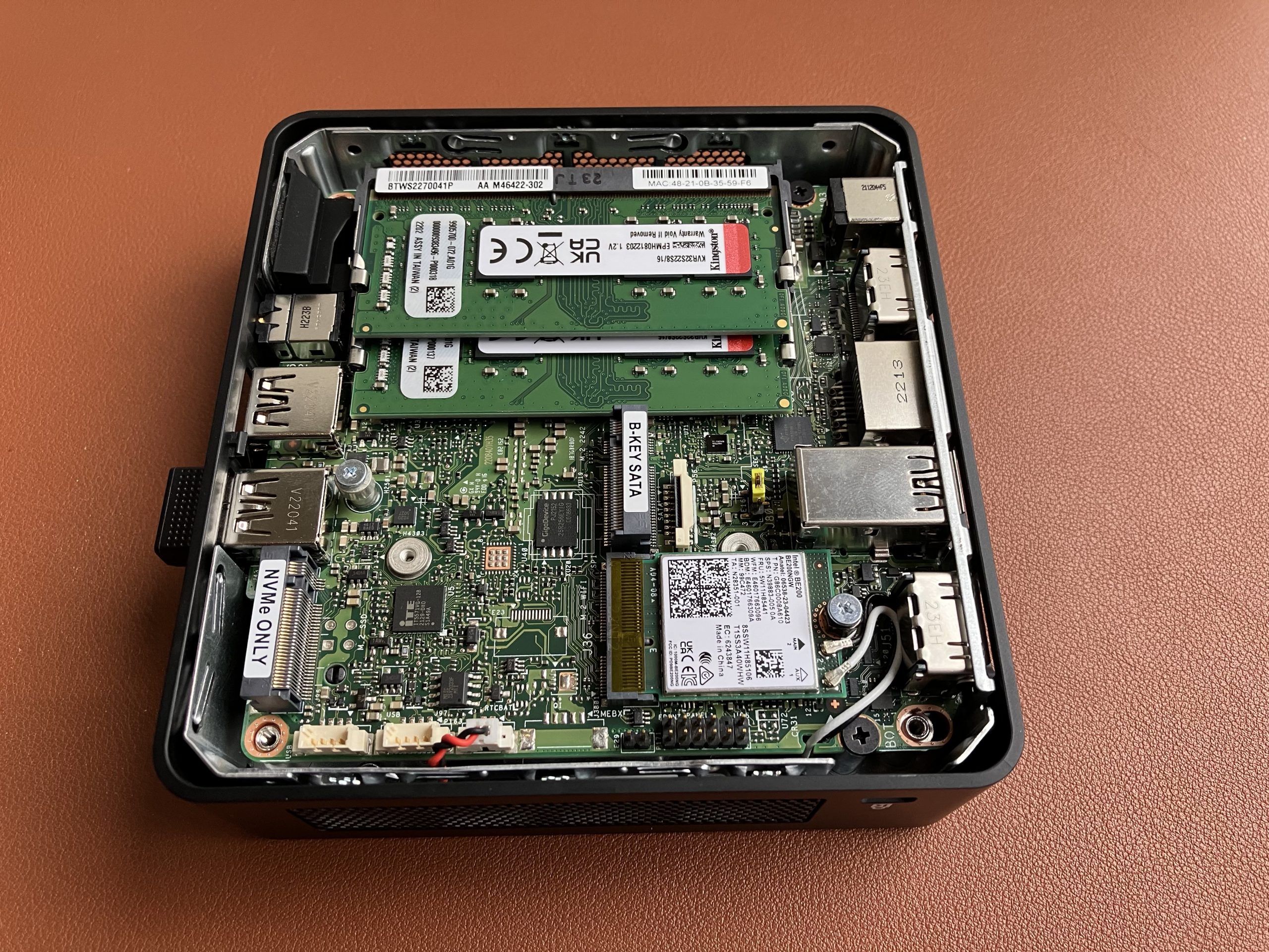
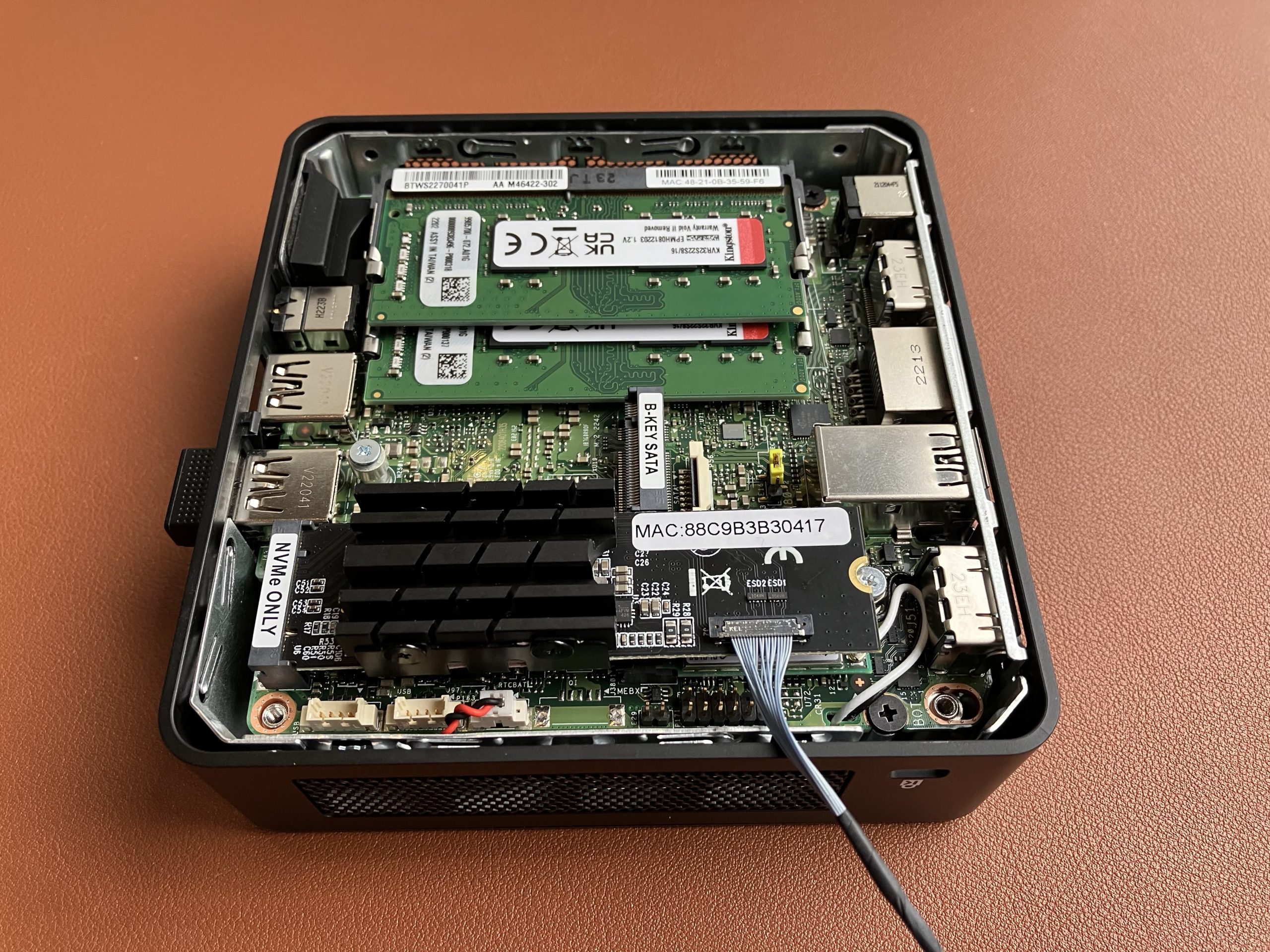
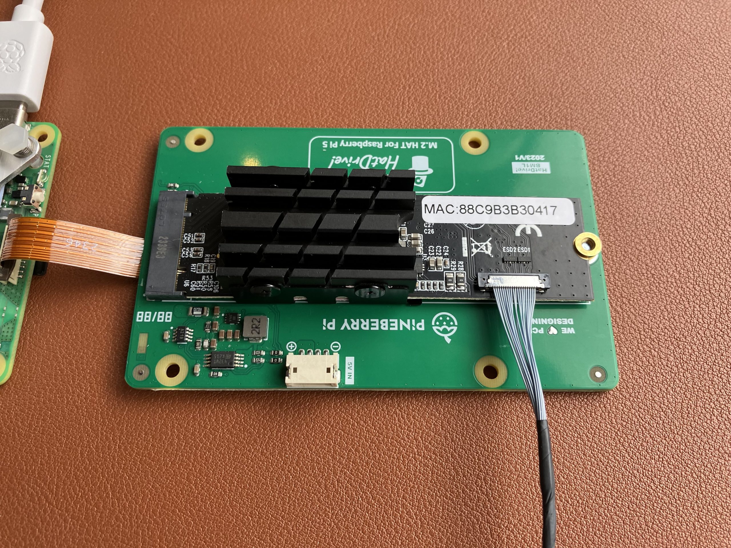
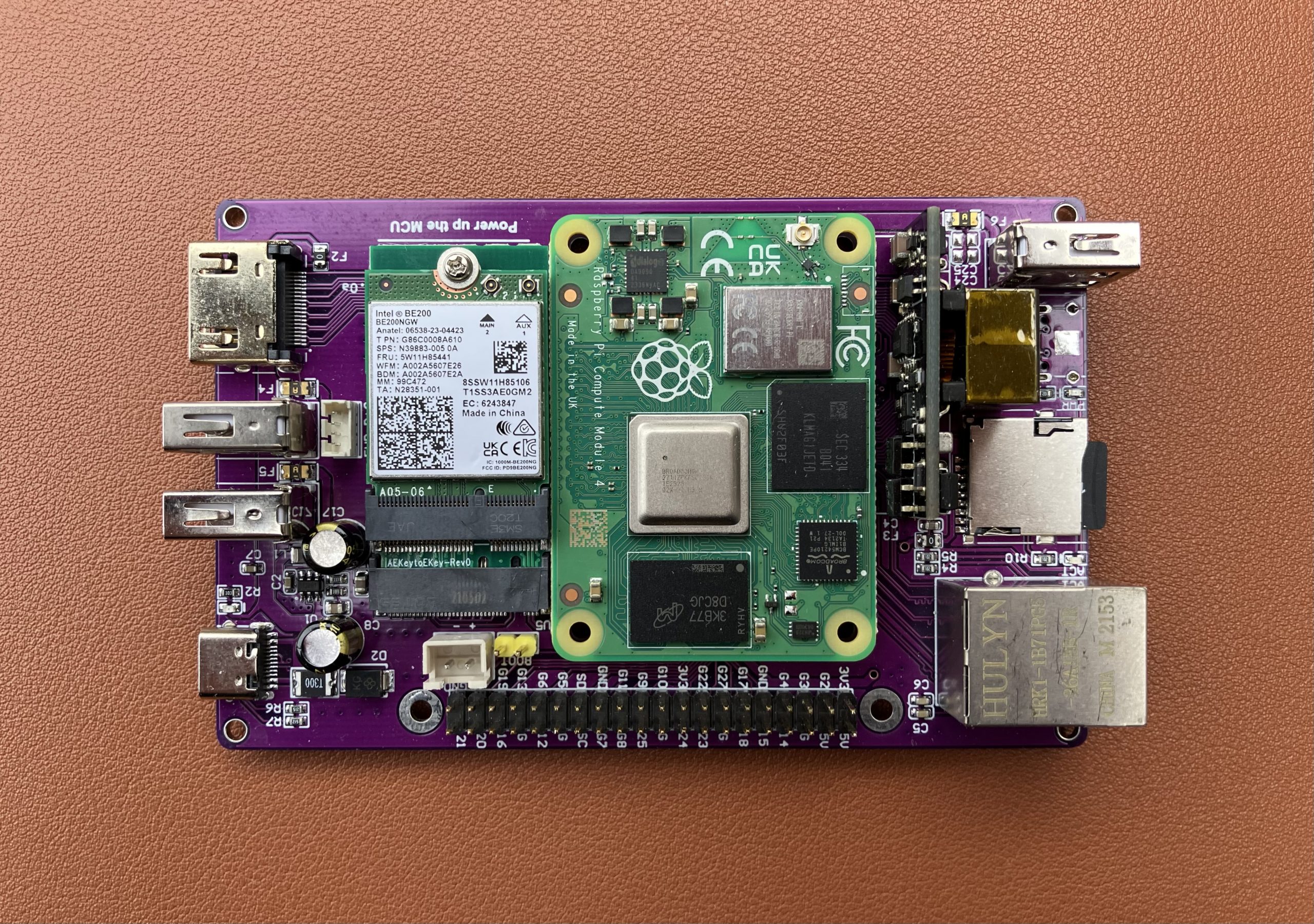
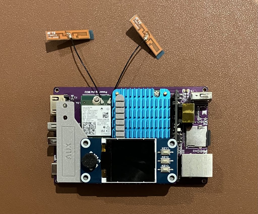
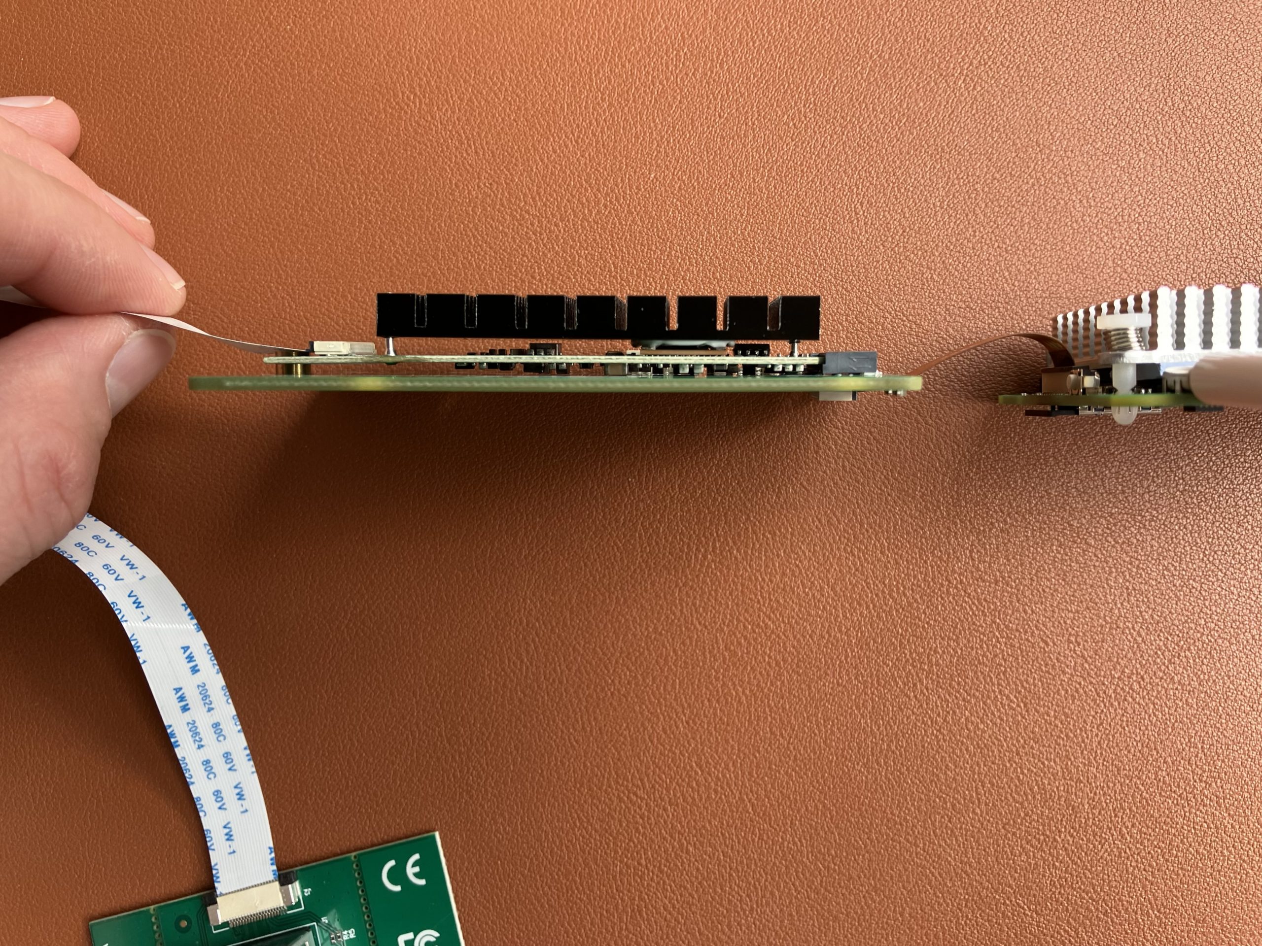
Look at this official product photo and my photo below. Spot one difference 😉

The official product photo

The actual correct setup

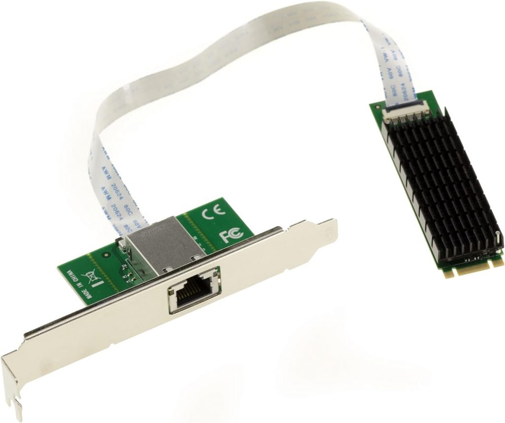
Did you notice the orientation of the white ribbon cable? The official photo got it wrong. The printed text on the cable needs to be on the top on one side, and on the bottom on the other one.

The eth1 interface and its IP details

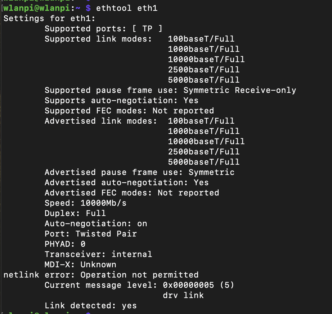
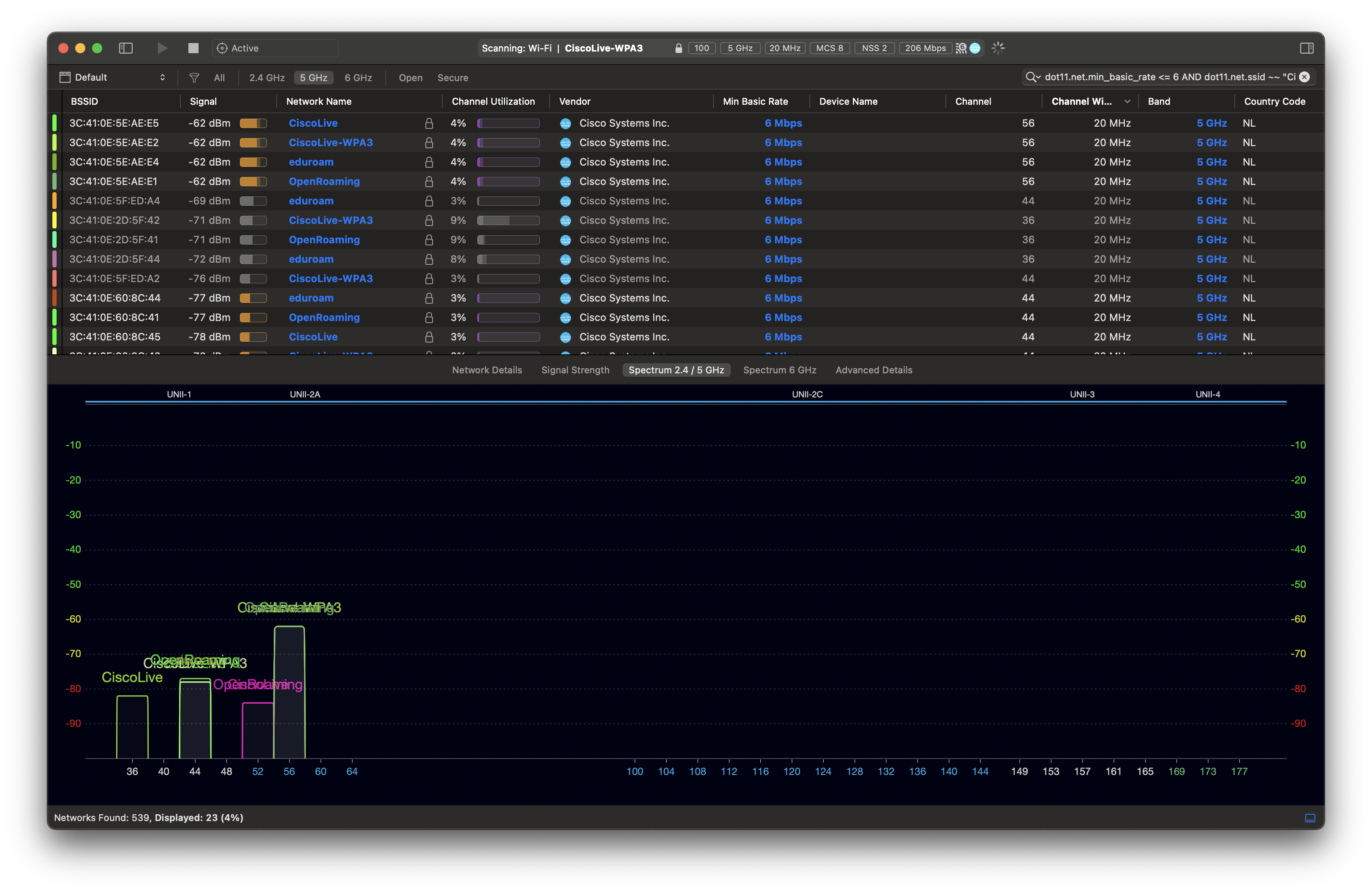
What speeds did you get in PCIe Gen 2 mode?

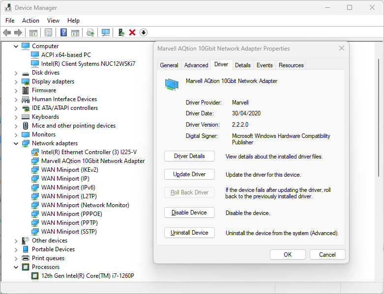
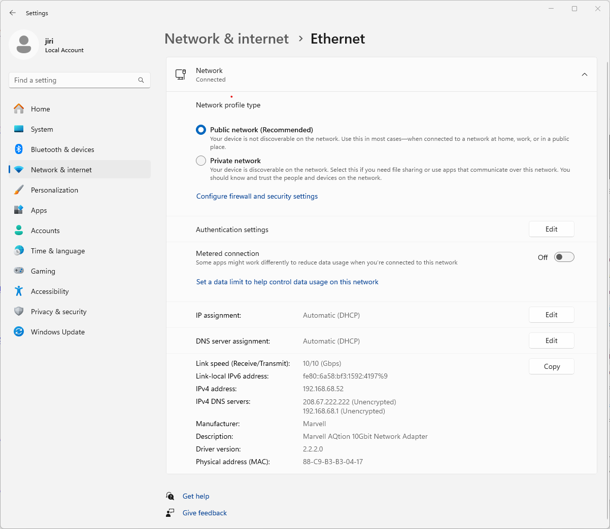
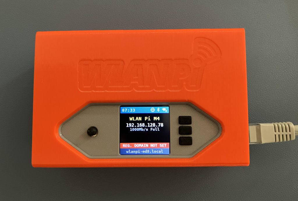
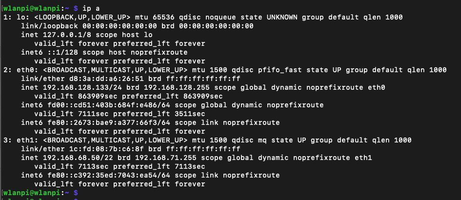
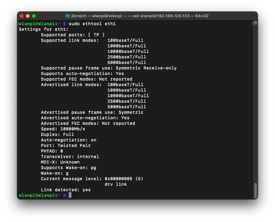
After correcting the orientation of the flexible cable, the interface came up, negotiated 10 Gbps full duplex.

10 Gbps full

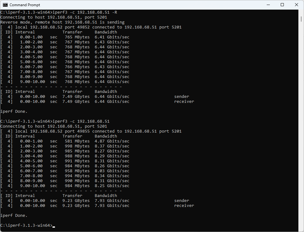
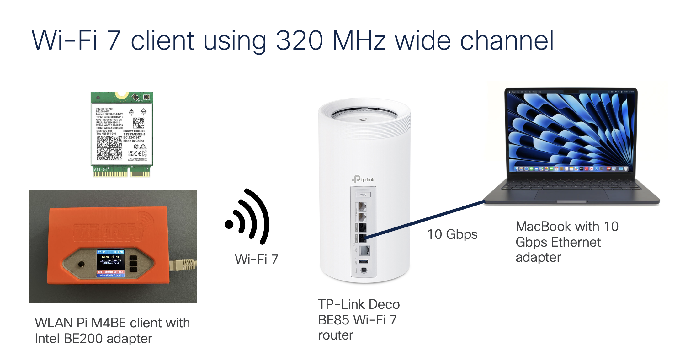
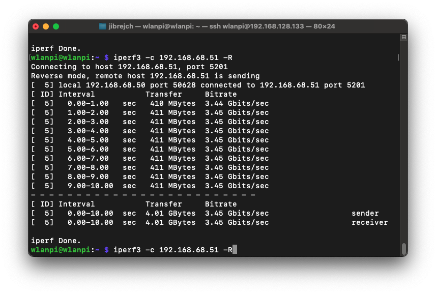
I started throughput testing against MacBook with my trusty 10 GbE Thunderbolt adapter.

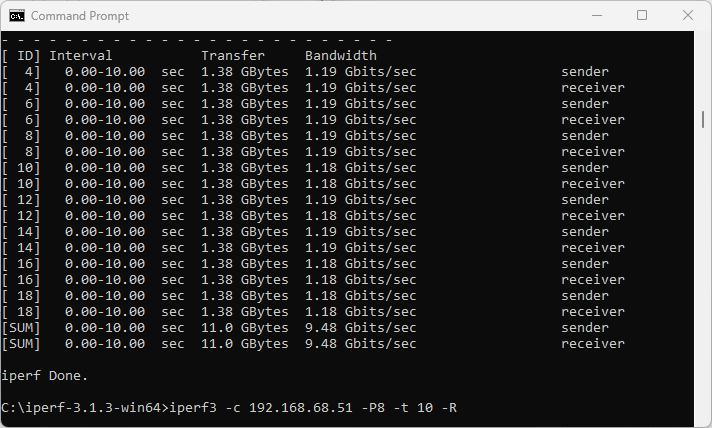
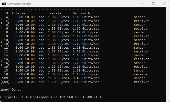
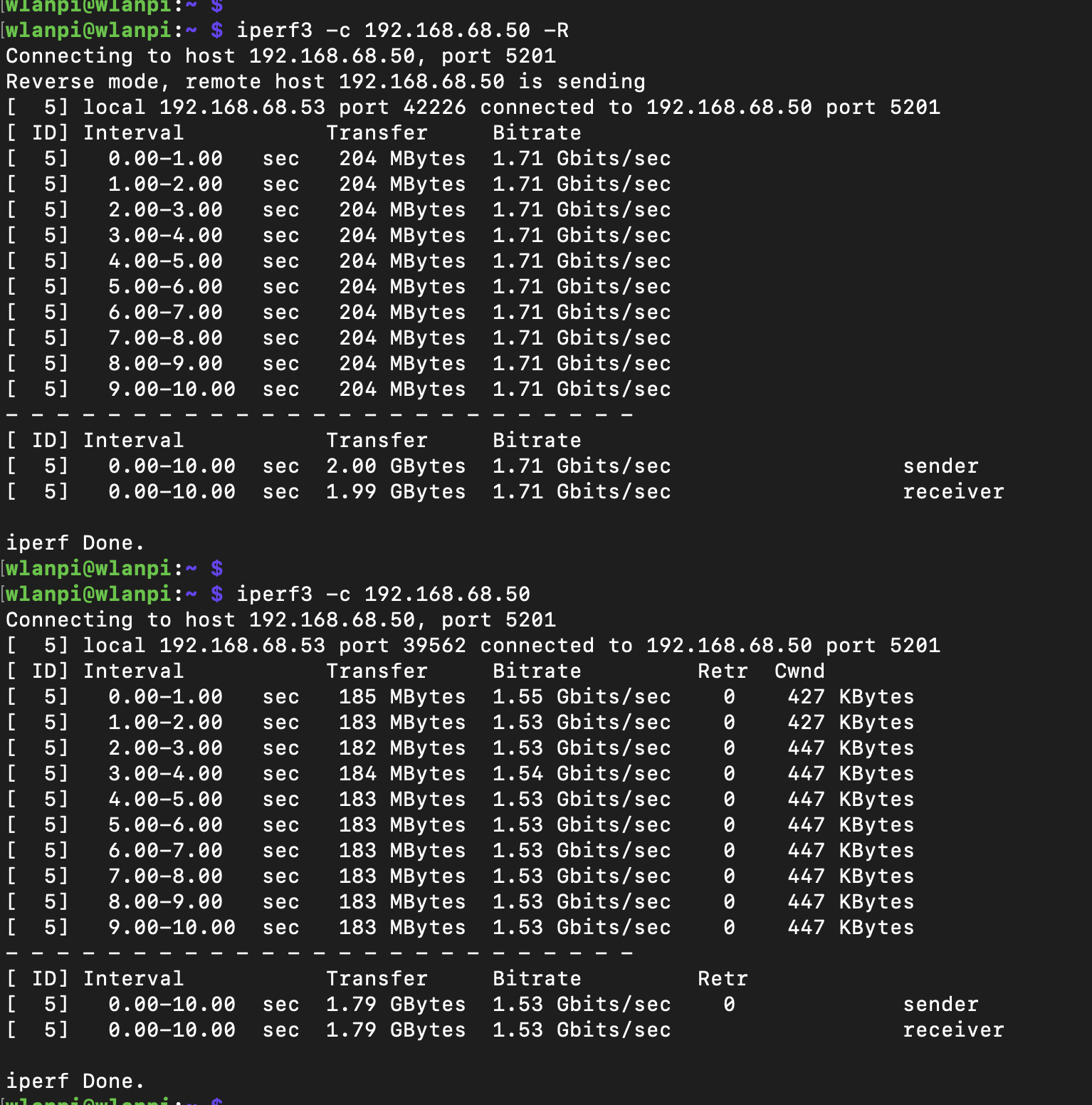
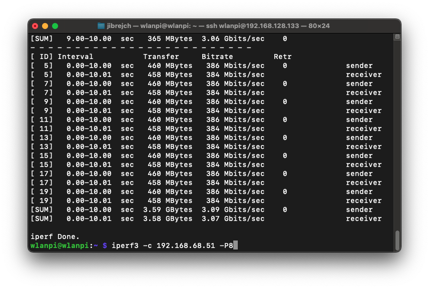
In PCIe Gen 2 mode, we got TCP throughput of 3.45 Gbps on the downlink and 3.07 Gbps in the upstream direction. Using more iperf3 parallel streams did not increase performance.

Downstream throughput

Upstream throughput

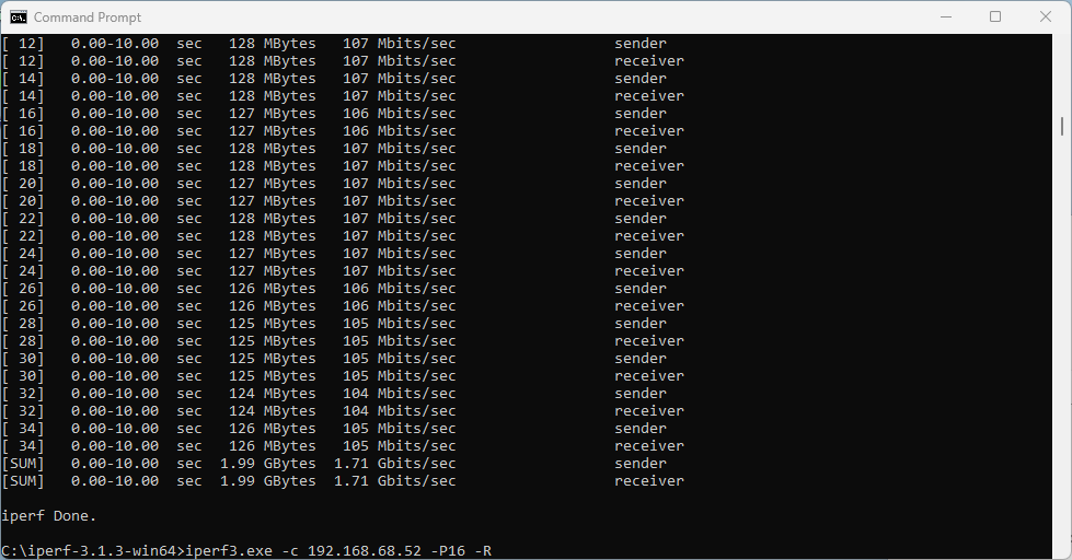
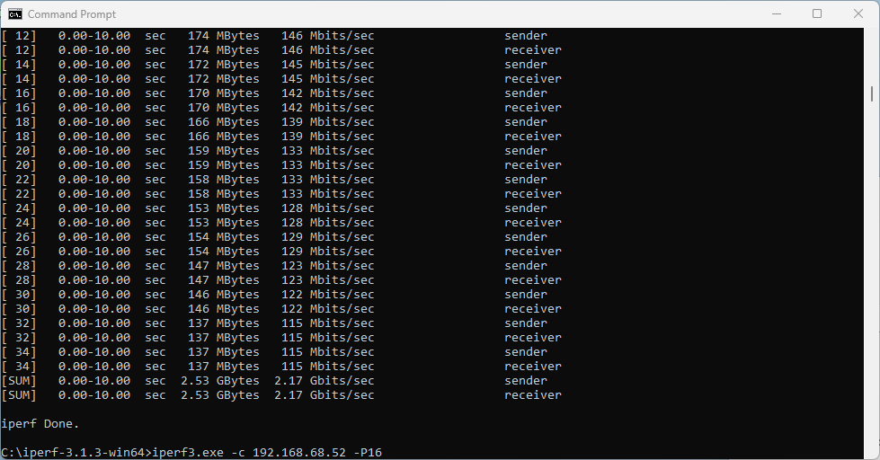
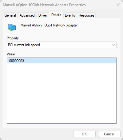
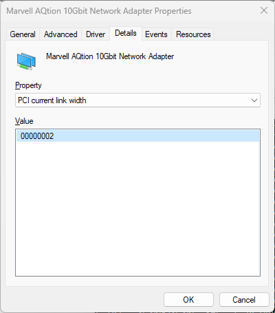
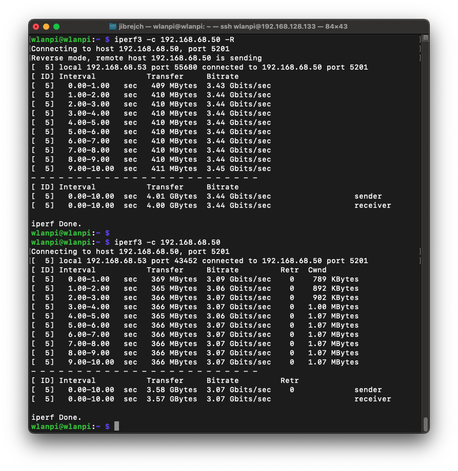
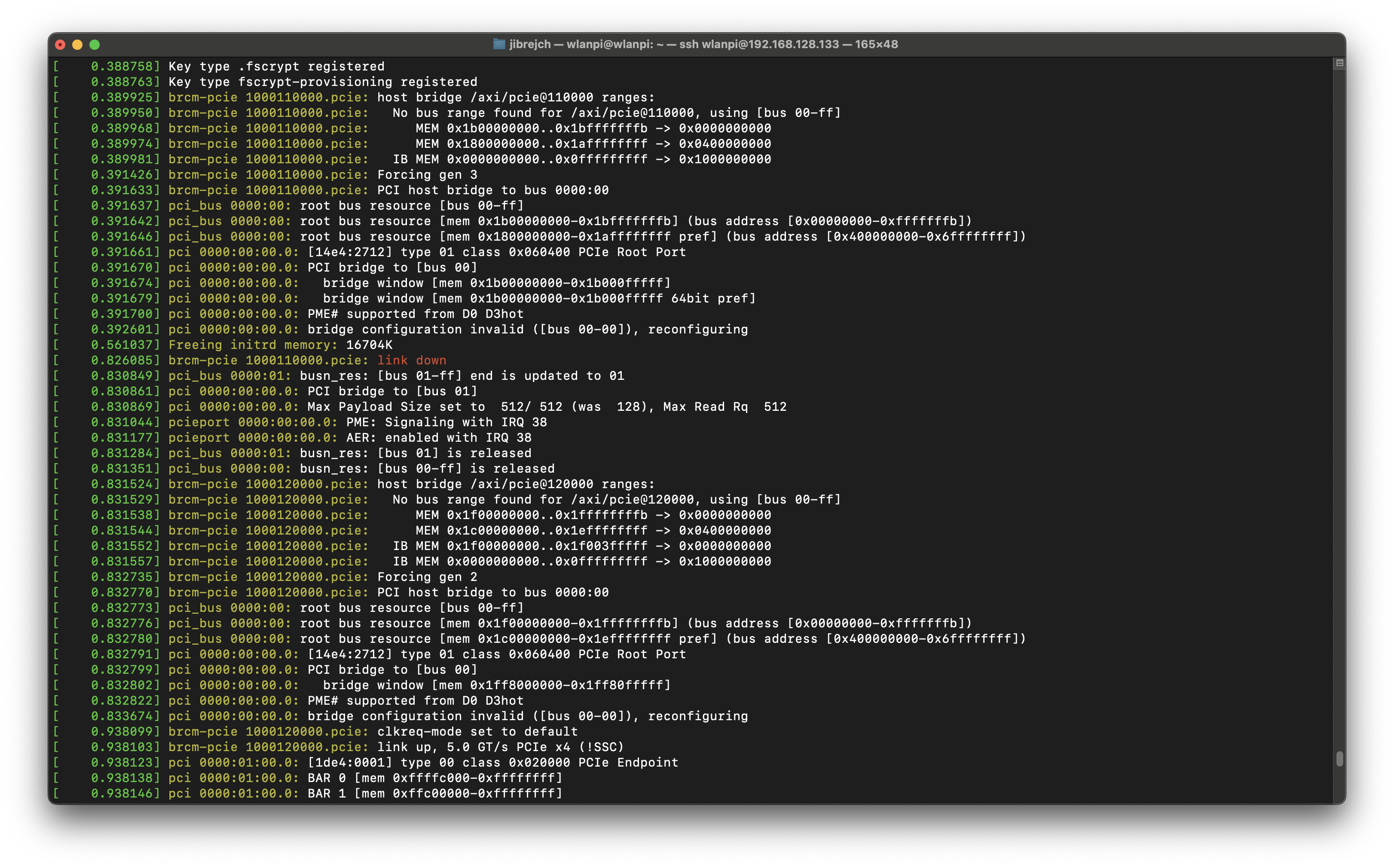
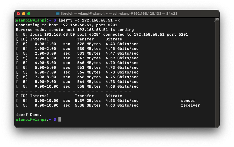
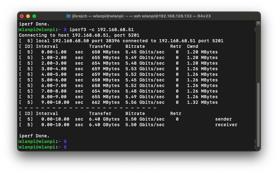
Were you able to use PCIe Gen 3 mode?

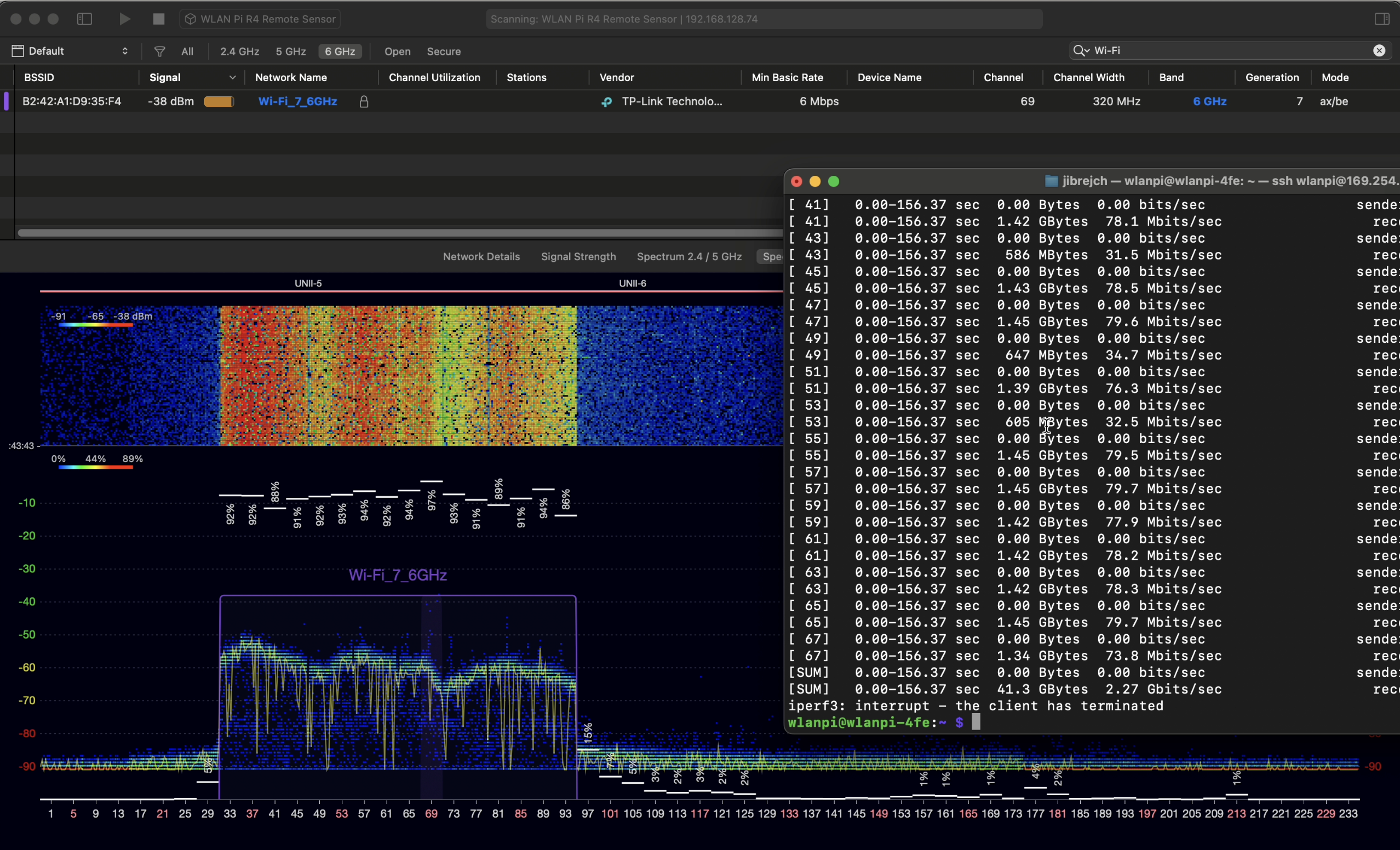
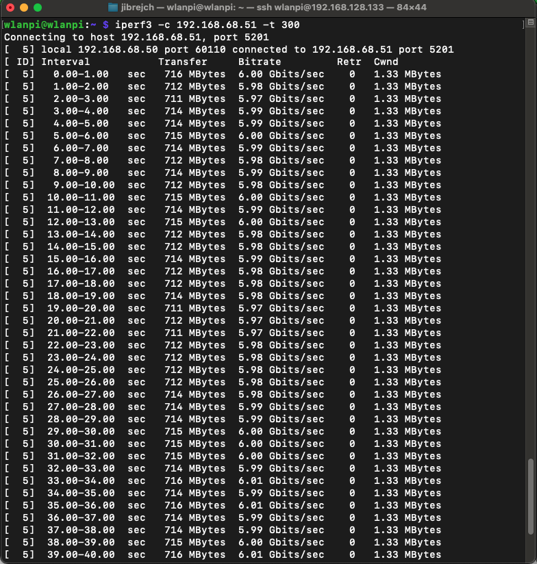
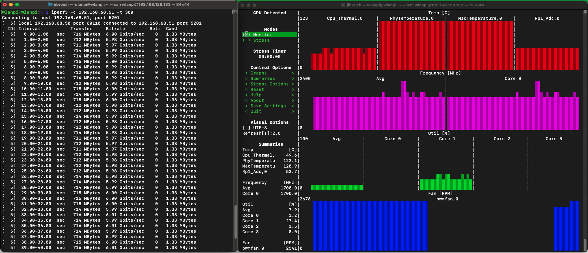
Yes! And I got 4.63 Gbps of TCP downstream and 5.5 Gbps (potentially up to 6 Gbps) upstream.

PCIe Gen 3 download
PCIe Gen 3 upload
I managed to get up to 6 Gbps in the upstream direction

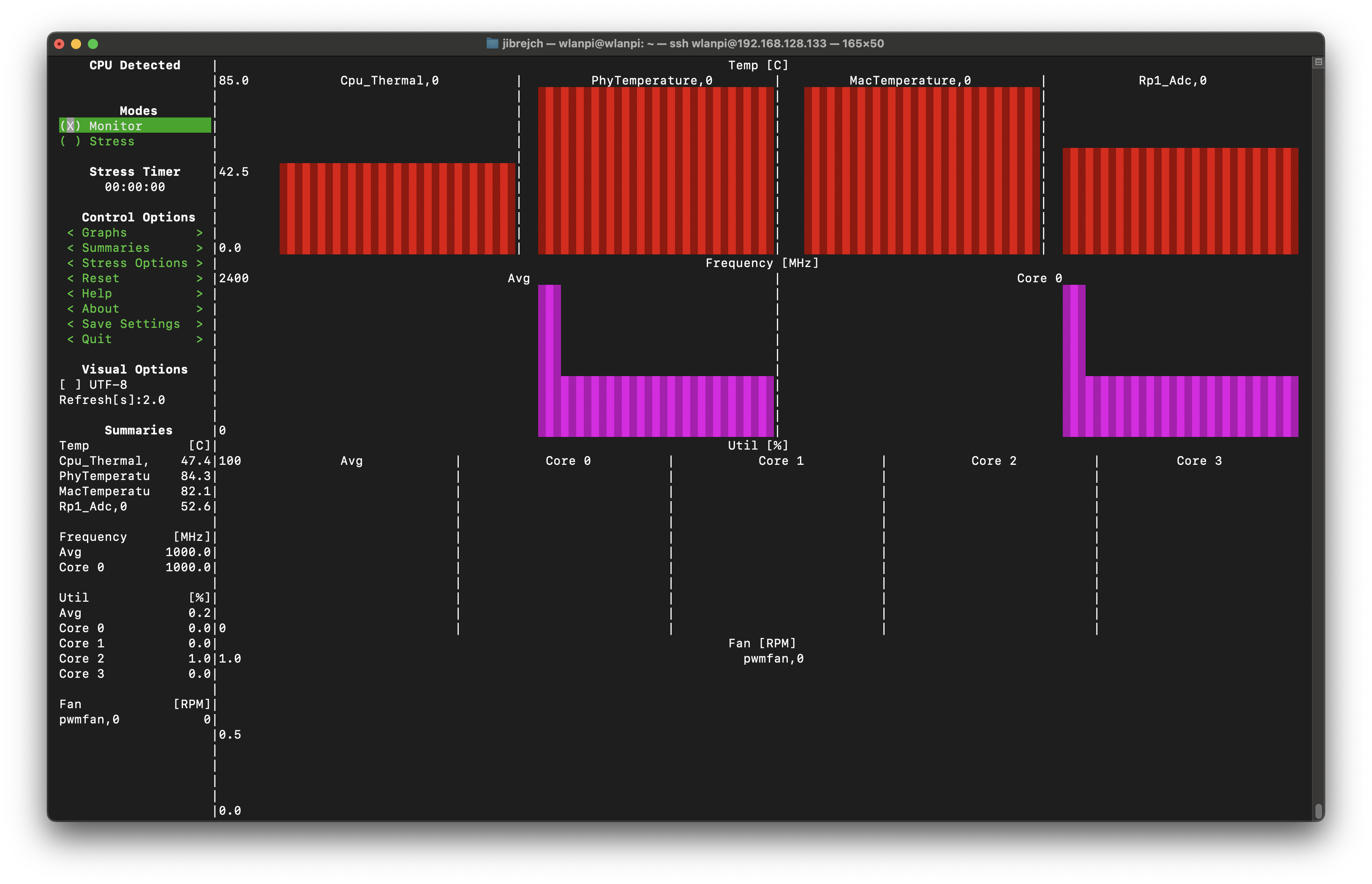
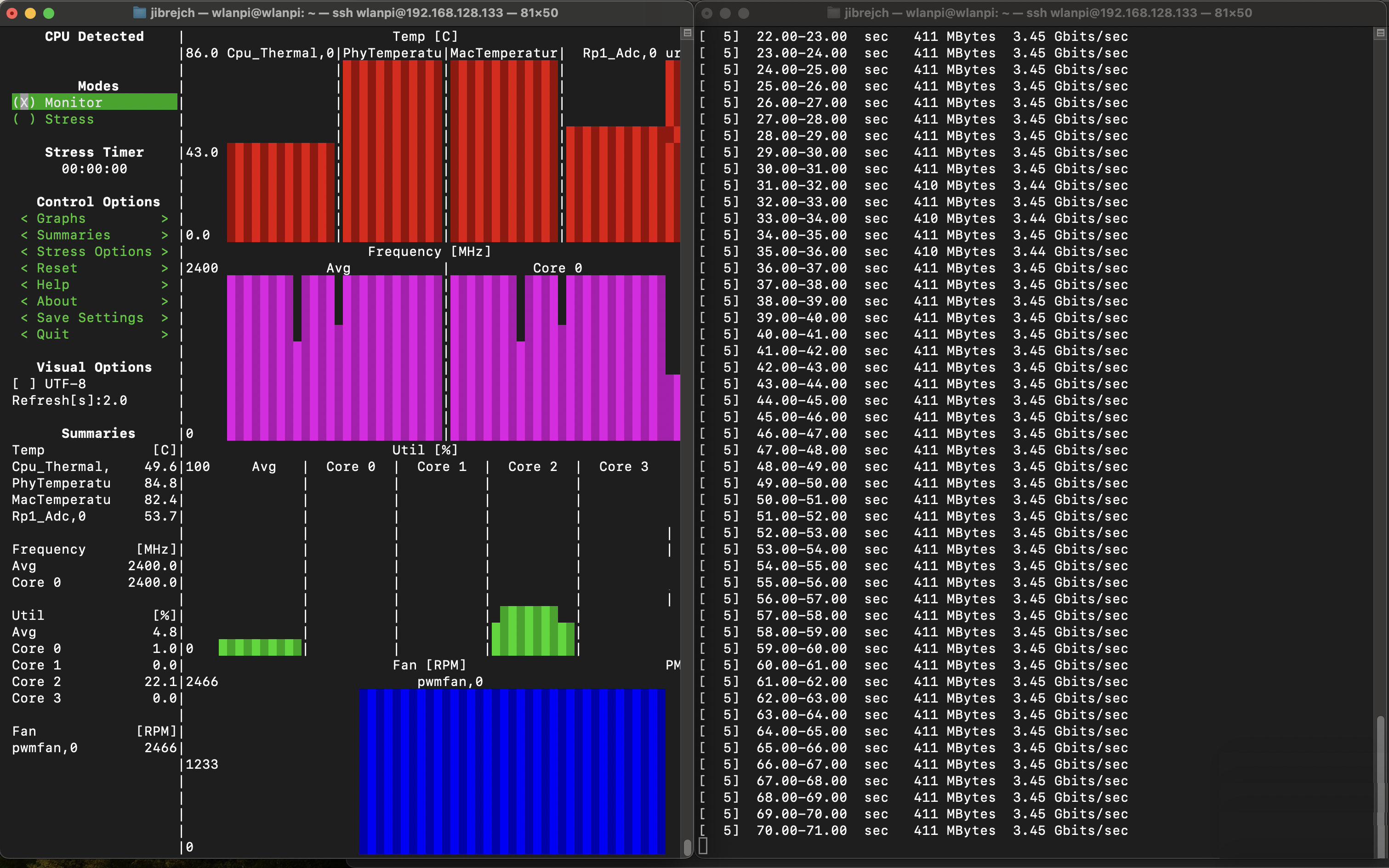
That’s hot news… yes 122° Celsius hot!

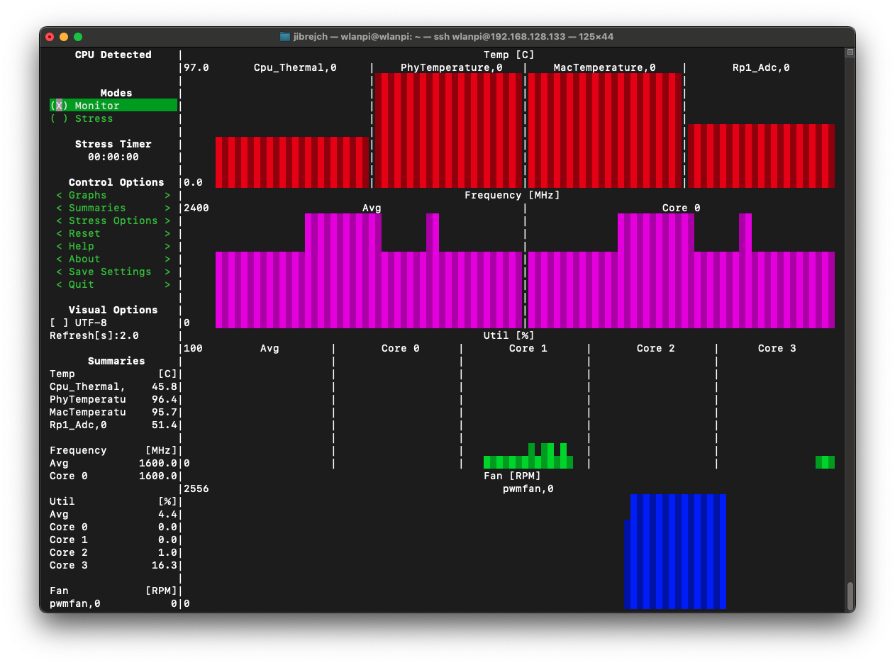
This adapter has a thermal problem. It comes with a heatsink, but even in idle mode it overheats.

Detail of the heatsink
107.7° C in idle

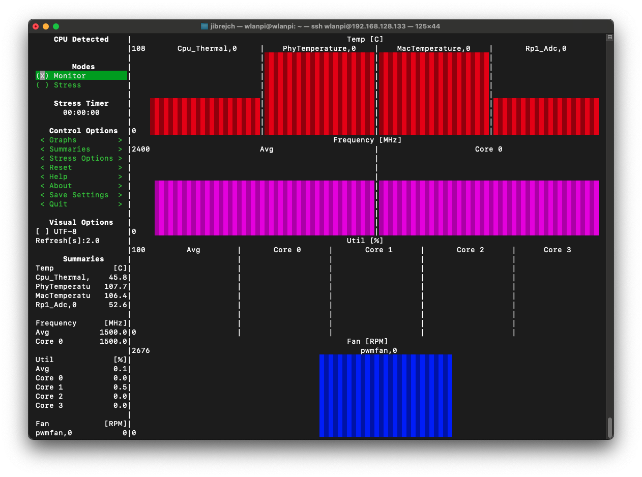
In PCIe Gen 3 mode with iperf3 test running, we are talking 122.1° C hot! The Pineberry board was very hot and you can literally burn your fingers by touching the heatsink.

122.1° C hot under load
In PCIe Gen 2 mode, it ‘only’ runs at 96.4° C

Long story short. Don’t buy this adapter, unless you want to add a fan or significantly larger heatsink.

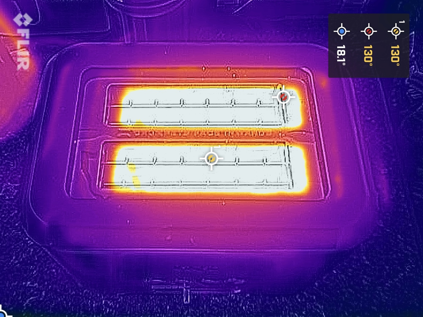
Toaster, 10 Gigabit adapter, aren’t they the same thing?

Make your own opinion based on these couple of thermal photos.

Thermal IR footprint of the Ethernet adapter
And here is a toaster for scale 😅

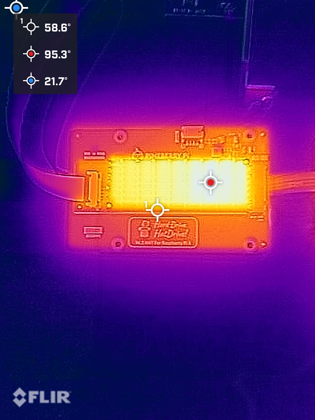
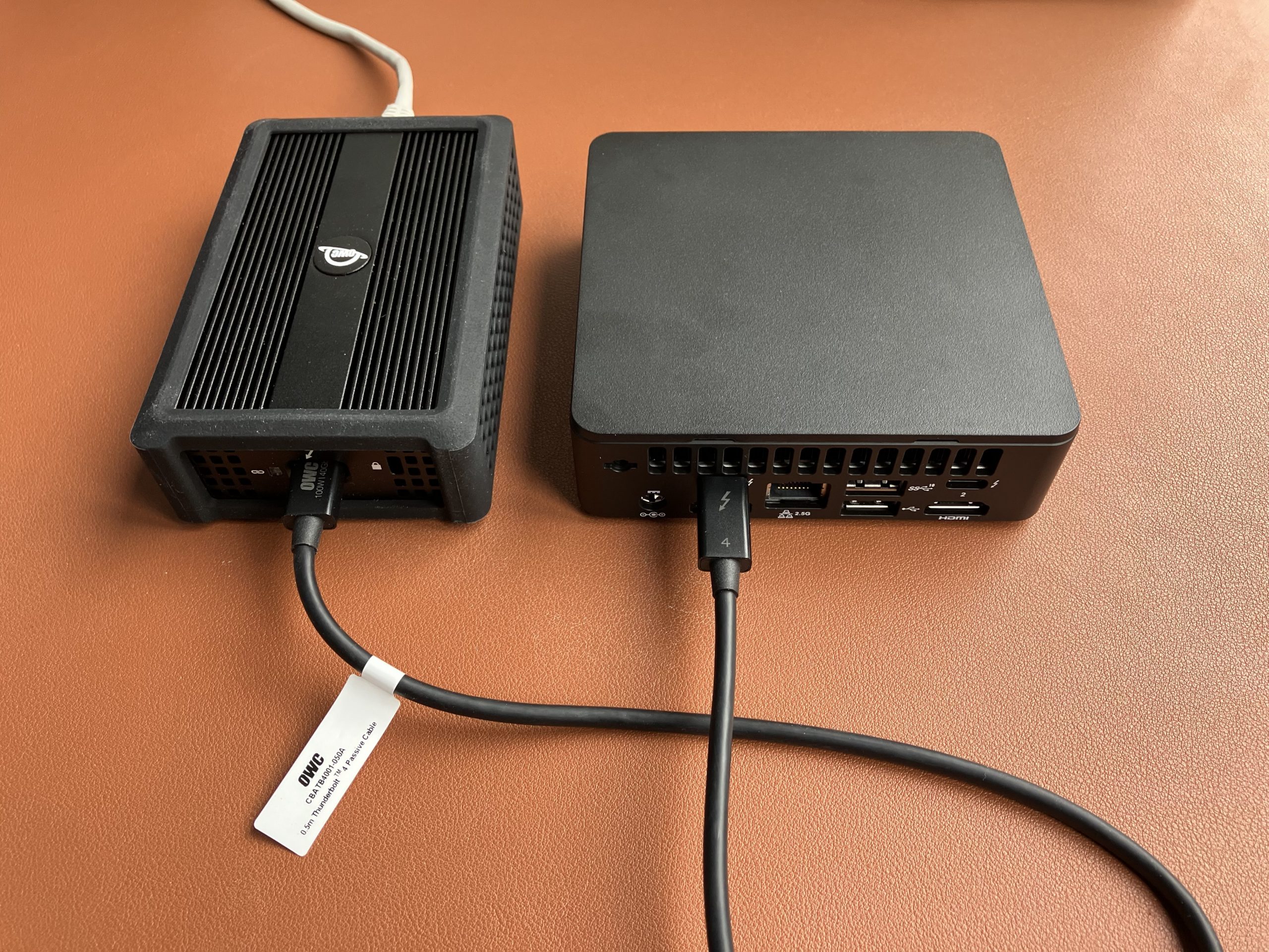
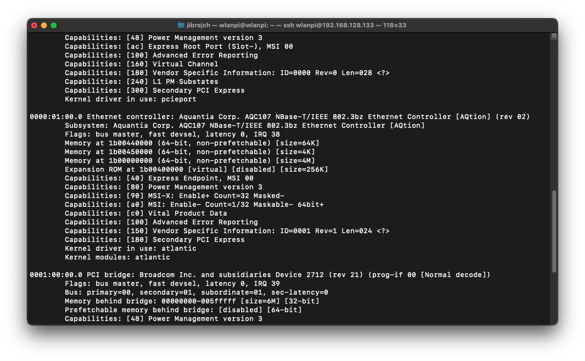
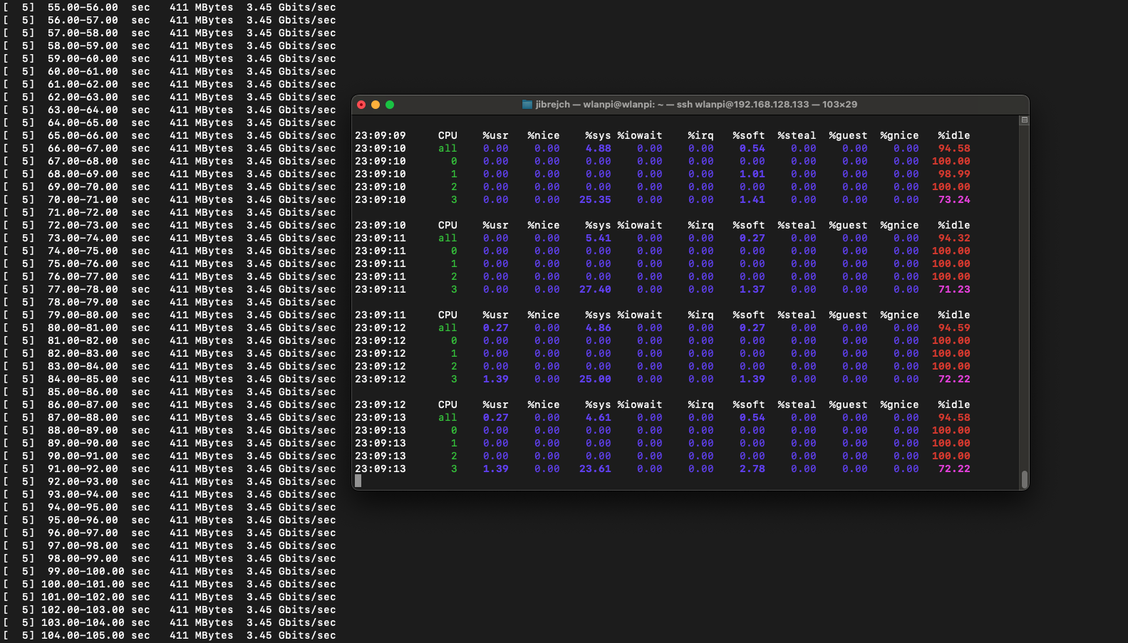
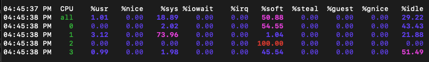
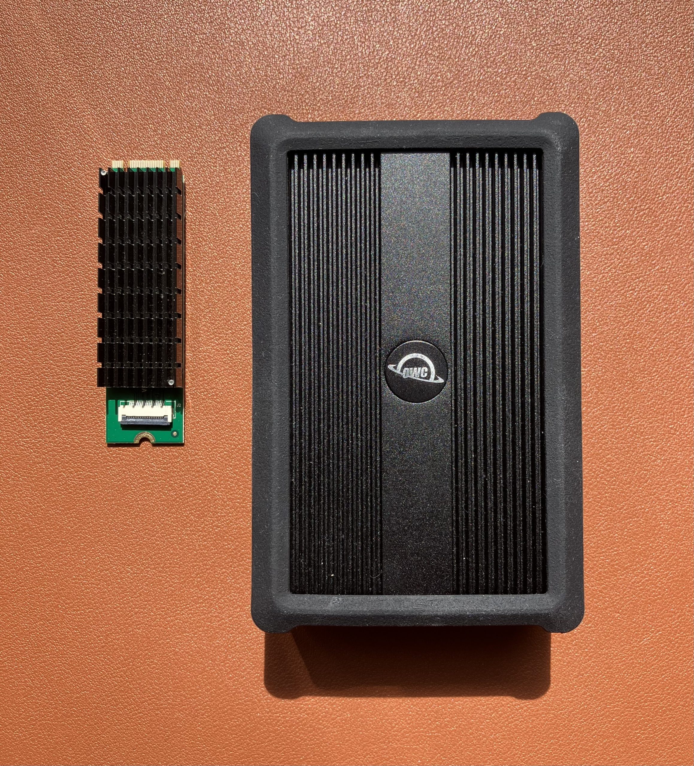
This Ethernet adapter as well as the OWC 10 GbE Thunderbolt both use the same Aquantia AQC107 (part of Marvell now) chip. It does really good job at keeping CPU utilisation low. I’ve seen much cheaper 2.5 GbE adapters that hammer CPU with interrupts until the CPU just can’t take no more.

But, compare size of the two heatsinks. Unlike this one, the OWC adapters delivers good thermal results. Don’t take me wrong, it still runs warm, but not anywhere near.

Same AQC107 chip, massive thermal mass difference

Summary

On the positive side, this is the first 10 Gigabit adapter I tested which actually worked in PCIe Gen 3 mode on Raspberry Pi 5. I got TCP throughput of up to 6.0 Gbps.

As far as I can tell, the limit of Raspberry Pi 5’s PCIe bus is around 6 Gbps if you look at it through the iperf3 TCP traffic lens. AQC107 silicon does an amazing job at keeping the Raspberry Pi’s CPU utilisation low. This helps us get as much throughput as we can from the Pi. But it produces a significant amount of heat.

The fact is that this adapter overheats. Don’t buy it unless you wish to use it with a fan or design a much larger heatsink yourself.

Wi-Fi 7 on Windows 11

The other week I tested Wi-Fi 7 on Linux. It worked great. Let’s see how Intel BE200 Wi-Fi 7 adapter performs on Windows 11 23H2.

Intel NUC 12th generation with Intel BE200 Wi-Fi 7 adapter

Drivers

Download and install latest driver from Intel’s website. Windows Update itself won’t install any driver, so some manual steps are required. I originally tested driver version 23.20.0.4, and now updated to 23.30.0.6.

Setup

We are using TP-Link Deco BE85 BE19000 consumer Wi-Fi 7 router connected to a 10 Gigabit iperf3 server running on MacBook connected via OWC 10 GbE to Thunderbolt adapter. We have done this on Linux before, so let’s see how the same Wi-Fi adapter performs on Windows.

Wi-Fi 7 on Windows 11 test topology

Performance

On the router, we have configured and verified 320 MHz wide Wi-Fi 7 channel. But when we connect the Windows client, looking at the data rate, it is surprisingly low – if you forgive me calling 2882 Mbps ‘low’ 😊 Considering that the NUC is about 1 meter away from the router, I would expect ~5 Gbps data rate. So what’s going on here?

Connected Wi-Fi 7 client, but low data rate

Interestingly enough, it is the same data rate as we see when connected using 5 GHz 160 MHz channel. Yes, I know, that’s a no-no in Wi-Fi design. We are just testing here.

Hmm, 160 MHz wide 5 GHz channel gives us the same data rate
netsh wlan show interfaces command output

Since Windows doesn’t expose the channel width in the UI, we don’t quite know what is happening on the air. Let’s generate some 6 GHz traffic, and check using Oscium’s WiPry Clarity tri-band spectrum analyser. I love this little USB tool. In this example I use a WLAN Pi as a Remote Sensor. It scans for Wi-Fi networks and streams spectrum information to WiFi Explorer Pro on Mac.

WLAN Pi Remote Sensor with Oscium WiPry Clarity scanning 6 GHz
Windows client is using 160 MHz instead of 320 MHz

Bingo! Apparently, on Windows Intel BE200 uses 160 MHz channel width and doesn’t support 320 MHz wide channel. That halves our data rate and throughput. I wish Windows made channel width more obvious in the UI. Intel BE200 adapter supports 320 MHz wide channels on Linux without a sweat, so hopefully it will get fixed in a future Intel driver or Windows release.

Updated: Apparently, I didn’t read Intel’s release notes closely enough, my bad 😊 Intel BE200 adapter on Windows 11 is only able to use Wi-Fi 6E today. Windows 11 will introduce Wi-Fi 7 support in a future update. Since Wi-Fi 6E supports channel widths up to 160 MHz, that’s why we are not being able to use full 320 MHz channel width. What really confused me was the “Protocol: Wi-Fi 7 (802.11be)” misleading Wi-Fi network status reported by Windows. Thank you Ben for spotting the note in Intel’s documentation.

What does that translate to? Lower data rate and lower throughput. I would expect download and upload to be around 2.5 Gbps using 320 MHz wide channel. With the latest Intel driver 23.30.0.6, we get 1.71 Gbps TCP download speed with 16 parallel streams, and upload of 2.17 Gbps. But only the upper 160 MHz half of the 320 MHz wide channel is used.

1.71 Gbps TCP download speed with 16 parallel streams
Upload TCP speed 2.17 Gbps with 16 streams

I also ran a quick Speedtest.net test (I know it is not a proper throughput testing tool) on a 900/900 Mbps WAN link.

On a Linux Wi-Fi 7 client, I measured nearly 890/890 Mbps. Original Intel driver 23.20.0.4 performed 383/818 Mbps. The latest Intel driver 23.30.0.6 delivered more symmetric numbers, and results were closer to the actual WAN link speed.

Speedtest.net speeds using the latest 23.30.0.6 Intel driver

Summary

Wi-Fi worked well, but application speeds including Speedtest.net and other tools performed quite poorly and subjectively ‘felt slow’. iperf3 test showed higher performance, but the main problem for the purpose of a throughput test is that the adapter only uses 160 MHz out of the available 320 MHz.

When it comes to recommended channel width in real world, it depends. 80 MHz or 40 MHz wide channels are most likely the best place to start depending on your circumstances and region.

For reference: Disable 6 GHz on Intel BE200 adapter

If you are performing tests on an SSID that has multiple bands enabled, and you want to force the client to drop off 6 GHz and join using a 5 GHz channel instead, Intel BE200 driver has the option to disable the 6 GHz band.

Disable 6 GHz band on Intel BE200

10 Gigabit Ethernet on Intel NUC

Earlier this week, I tested a 10 Gigabit Ethernet M.2 network adapter on Raspberry Pi 5, and it didn’t quite cut it. Mainly due to limited PCIe Gen 2 performance. Now, the question is can this 10 Gigabit adapter actually push 10 Gbps of traffic at all?

To find out, we are going to slightly reconfigure this Intel NUC 12th generation mini PC. It has an M.2 M-key slot for NVMe drive. Let’s use this slot for our 10 GbE adapter. And we will boot Windows 11 off an external USB SSD drive.

Remove NVMe from the M.2 slot
Install 10 GbE network adapter instead
Intel NUC with 10 GbE adapter connected to 10 GbE switch

Install Windows 11 23H2 version on a USB SSD drive, boot Windows, run Windows Update, voila!

Windows Update installed latest driver automatically
It uses PCIe Gen 3
And x2 link width
10 Gbps Full Duplex

With default iperf3 settings we get 6.44 Gbps/7.93 Gbps in the downlink and uplink direction respectively. Not bad, but is that it? Of course not.

iperf3 with default settings

I don’t really want to enable Jumbo frames as it’s not always possible to enable Jumbo frame support end-to-end, especially if part of the network doesn’t support it or isn’t under your management. Fortunately, 8 parallel TCP streams in iperf3 do the trick for us. We get 9.48 Gbps download speed.

9.48 Gbps download

In the upstream direction from this NUC to my MacBook with 10 GbE adapter, we also get 9.48 Gbps. I am happy. You? 😉

9.48 Gbps upload

Summary

After all, this 10 GbE M.2 network adapter is indeed capable of pushing 9.48 Gbps of traffic in either direction. But! It is not really a good choice for a system like Intel NUC. I can’t pop the lid back on, the heatsink is too tall. Frankly, I can’t recommend this adapter at all. It runs hot at 84° Celsius in idle.

If you are looking for a daily driver, and your system supports Thunderbolt, get yourself this OWC 10GbE to Thunderbolt adapter. Here is my test. It works out of the box on Windows (I tested this Intel NUC 12th Gen) and macOS (I tested MacBook Pro M1 and M2). Interestingly, it uses the same chip as the above M.2 adapter. Just compare the two products and their heatsink sizes. The AQC107 keeps the main CPU utilisation very low, but it produces a significant amount of heat.

OWC 10 GbE to Thunderbolt network adapter connected to Intel NUC
OWC 10 GbE to Thunderbolt network adapter connected to MacBook

10 Gigabit Ethernet on Raspberry Pi 5

Raspberry Pi 5 comes with PCI Express connection and a number of HATs (hardware attached on top) and Bottoms (the opposite of that) are now available for sale. That unlocks some very exciting options. Let’s see how fast can a 10 Gigabit Ethernet adapter on Raspberry Pi 5 go, shall we?

Pineberry’s HatDrive! Bottom proved to be really handy for converting Pi’s PCIe connection to M.2 M-key format. My Kalea-Informatique 10 Gigabit adapter uses exactly that, so that’s a match. Why did I choose this adapter? Very unscientifically this time – it was the first readily available and I was in a fail-fast mood :)

10 GbE adapter connected to Raspberry Pi 5
Pineberry HatDrive! Bottom board with 10 GbE network adapter
Detail of the AQC107 chip powering the network adapter

Enable PCIe port on Raspberry Pi 5

First things first. We need to enable the PCIe connector on the Pi.

sudo nano /boot/firmware/config.txt

# Enable the port
dtparam=pciex1

# Configure PCIe Gen
dtparam=pciex1_gen=2
Enable PCIe and configure mode

Build custom Linux kernel and include the Aquantia driver module

Vanilla Raspberry Pi OS doesn’t include the Aquantia AQC107 kernel module. So we need to burn a micro SD card with a vanilla Raspberry Pi OS Bookworm image, boot the Pi 5 and build a customised kernel.

git clone --depth=1 --branch rpi-6.8.y https://github.com/raspberrypi/linux
cd linux/
sudo apt install flex bison aptitude -y
sudo aptitude install libssl-dev
make bcm2712_defconfig

Edit the config file:

sudo nano .config

Add these 2 lines to .config file:

CONFIG_AQTION=m
CONFIG_AQUANTIA_PHY=m

Trigger customised kernel build on the Pi. This will take some time, so bear with us, please.

sudo make -j4 Image.gz modules dtbs
sudo make modules_install
sudo cp -v arch/arm64/boot/dts/broadcom/*.dtb /boot/firmware/
sudo cp -v arch/arm64/boot/dts/overlays/*.dtb* /boot/firmware/overlays/
sudo cp -v arch/arm64/boot/dts/overlays/README /boot/firmware/overlays/
KERNEL=kernel_2712
sudo cp -v arch/arm64/boot/Image.gz /boot/firmware/$KERNEL.img
uname -a
sudo reboot

After reboot, the LED light on the network adapter should come to life and we can capture first impressions.

Adapter recognised
10 Gbps Full Duplex
lspci -v output

Temperature

First thing you will likely notice is how hot this network adapter runs. It runs at 85° Celsius in idle which is slightly worrying and you can literally burn your fingers if you are not careful. Thumbs down on the thermal design front.

High idle temperature

Under load, surprisingly, it ‘only’ runs 0.5° warmer.

High temperature under load

How fast can it go then?

Raspberry Pi 5 officially supports PCIe Gen 1 and Gen 2. It is not certified for Gen 3.

PCIe Gen 1 mode

In this slowest mode, I got 1.71 Gbps/1.53 Gbps iperf3 TCP results with standard iperf3 settings. No jumbo frames, no other tweaks.

PCIe Gen 1 throughput

PCIe Gen 2 mode

Again, with standard iperf3 settings, I measured 3.44 Gbps/3.04 Gbps TCP throughput between 2 computers both connected to 10 Gbps switch ports via 10 GbE Full Duplex.

PCIe Gen 2 throughput

In idle conditions, this setup draws 7.5 W, and 8.9 W under 10GbE adapter iperf3 -R load (3.45 Gbps). Using more iperf3 parallel streams (the -P parameter) did not help at all.

Power draw

PCIe Gen 3 mode

The adapter supports PCIe Gen 3, but it doesn’t work with the Pi. The Pi is not certified for Gen 3, so I can’t say anything bad about this. The Ethernet adapter is not recognised in Gen 3 mode, and no interface is present in ip a. Sometimes the Pi will fail to boot.

According to dmesg, the Pi forced Gen 2 mode:

brcm-pcie 1000110000.pcie: link down
brcm-pcie 1000120000.pcie: Forcing gen 2
Forcing PCIe Gen 2 mode athough Gen 3 has been configured

I powered my Pi from M2 MacBook USB-C port. So I thought, I might be running into under-voltage issues. I tested the official Raspberry Pi 27 W (5 V * 5 A) AC power and it made no difference.

Did you upgrade Raspberry Pi 5 firmware?

Yes, I did. It is running the latest version available as of March 2024.

Latest firmware installed

Low CPU utilisation

One feature I really enjoyed is the extremely low CPU utilisation under load. I saw slower 2.5 GbE adapters hammer CPU with interrupts, but that’s not the case for this NIC. AQC107 does really good job at keeping the CPU cool.

Low Raspberry Pi 5 CPU load under network load

Cable analytics

Marvell supports Cable Diagnostics feature which uses TDR to measure cable length and detect Ethernet cable for defects. Unfortunately, it doesn’t seem to be supported on the AQC107 chip.

Cable Diagnostics not supported

Can you get 10 Gbps out of this adapter at all?

I am glad you asked. How does an Intel NUC with this 10 GbE adapter sound? I’ve just tested it, here you go.

Intel NUC with 10 GbE adapter

Summary

The high operating temperature really makes this adapter something I can’t recommend. With maximum throughput below 3.5 Gbps, I think you would be better off choosing a 2.5 Gigabit Ethernet adapter, which runs cool and delivers 2.35 Gbps/2.35 Gbps throughput.

Have you tested any other 10 GbE adapter? Did you get better results? Did you find any 2.5 Gbps Ethernet adapter that supports Cable Diagnostics? I am all ears.

Special thanks

Thanks to Luke Jenkins for exploring and sharing the kernel build instructions. Also, thanks to the WLAN Pi team. You can buy the team a coffee using this link.

Wi-Fi 7 comes to WLAN Pi M4

With the WLAN Pi team, we have designed and launched a M.2 adapter from A-key to E-key, which allows you to install a certified Wi-Fi 7 adapter Intel BE200 to your current WLAN Pi M4.

WLAN Pi M4

Is WLAN Pi selling ‘keys’ now? 😉

What is a ‘key’? It is formed of the notch on the Wi-Fi adapter PCB, and plastic blob separating pins inside the M.2 slot. The idea is to prevent users from plugging incompatible cards to the slot, and avoid any ‘magic smoke events’. Here is more about M.2 and the individual key types if you are interested.

WLAN Pi upgrade kit

Since Intel adapters use E-key and WLAN Pi M4 uses A-key, we needed to build an adapter. Badger Wi-Fi has the upgrade kit in stock. It comprises of the Oscium M.2 A-key to E-key adapter, Intel BE200 Wi-Fi 7 adapter, and 2 little bolts to secure the adapter and the Wi-Fi module.

Here is how the ‘butterfly’ setup looks like. Intel BE200 sits onboard of the A-key to E-key adapter, installed in the M.2 slot.

We are ready to connect existing tri-band antennas, and assemble the unit.

Software support

Make sure to either upgrade Linux packages to their latest versions using sudo apt update && sudo apt upgrade command, or download and flash the latest WLAN Pi software image on your SD card. Release 3.2.0 supports Wi-Fi 7 Intel BE200 adapter out of the box with no effort whatsoever on your part.

Wi-Fi 7 in action

For this demonstration I use a consumer Wi-Fi 7 router TP-Link Deco BE85 BE19000. Simply because it is available, Wi-Fi 7 certified, and it supports 320 MHz channel width – not that one would deploy that in an enterprise environment, but mainly to test the maximum Wi-Fi throughput of the Pi.

A bug in macOS doesn’t allow Macs to correctly recognise Wi-Fi 7 networks. Instead of Wi-Fi 7 320 MHz wide network, my MacBook reports Wi-Fi 6 and 160 MHz wide channel. So, we will use another WLAN Pi and its Wi-Fi radio as a Remote Sensor in WiFi Explorer Pro – you need the Pro version to do this.

Nice, Wi-Fi 7 AP!

Wi-Fi 7 network

Connecting the WLAN Pi as a Wi-Fi 7 client only takes few lines of wpa_supplicant config.

sudo nano /etc/wpa_supplicant/wpa_supplicant.conf
Wi-Fi 7 network settings

And we have successfully connected the WLAN Pi as a Wi-Fi 7 client to the AP using this command.

sudo wpa_supplicant -c /etc/wpa_supplicant/wpa_supplicant.conf -i wlan0
WLAN Pi connected as a Wi-Fi 7 client

Run this command to make sure the WLAN Pi requests an IP address from DHCP server running on the router:

sudo dhclient -i wlan0 -v

What channel are we using? 320 MHz channel width? Indeed.

Adapter and channel details

Before you ask, distance between the Pi and the router is sub 1 meter. What is the Wi-Fi data rate? We are using Wi-Fi 7 (EHT), 2 spatial streams, MCS 12 and 4096-QAM and short guard interval of 0.8 µs.

Data rates

We can refer to Francois Verges’ MCS index tool to check how we are doing. Yes, I have tried, but I have only been able to achieve MCS 13 extremely rarely.

MCS table

How far from the AP can we maintain 4096-QAM?

I hardly ever achieved MCS 13. To maintain MCS 12, I had to stay within about 1.5 meter distance from the router. I got best results with antennas position in this ‘V’ pattern.

V-shaped antenna placement

With a different client device designed for Wi-Fi 7 from the ground up (with professional quality antennas and placement), I would hope for slightly longer MCS 12 and MCS 13 range.

It’s throughput test time

It’s time to run an iperf3 test and see how much traffic we can actually push over the air and also how much the WLAN Pi M4 can handle. Here is our test setup. I recommend the OWC 10 GbE Thunderbolt adapter (it uses Thunderbolt protocol, not USB) connected via USB-C to your Mac.

With the help of Oscium WiPry Clarity 6 GHz spectrum analyser connected to another WLAN Pi, we can monitor the life spectrum and see how much red the iperf3 test introduces. We are able to achieve download TCP speed of 2.27 Gbps and upload speed of 1.74 Gbps.

I used iperf3 -c 192.168.68.51 -P32 -R to test download speed, and iperf3 -c 192.168.68.51 -P32 for upload. Number of parallel streams set to 32 provided the best performance.

Summary

Wi-Fi 7 works well on the WLAN Pi M4. In fact, it works better than Wi-Fi 7 on Windows 11. We have covered Intel BE200 on Windows 11 in this blog posts.

I was expecting 2.5 Gbps-ish throughput, which we have got quite close to. During the test, CPU of the WLAN Pi was running around 80 % utilisation, and interrupts were reaching 100 %. So, hardware of the WLAN Pi itself posed a bottleneck.

mpstat 1 300 -P ALL
High CPU utilisation due to interrupts

Orientation of the antennas mattered more than I expected to. Best position was a ‘V’ shape with antennas positioned away from the board. With AUX antenna placed 90 degrees relative to the Main antenna, data rates and throughput dropped. Perhaps there is RF noise from the board itself coming into play.

Apple iOS Shortcut: Install Wi-Fi diagnostics profile to your iPhone the easy way

Apple developed a diagnostics profile that allows you to monitor and troubleshoot Wi-Fi connectivity. Unfortunately, it is only available for 7 days after installation. After that, it get automatically removed. If you are a Wi-Fi professional, that means that you need to reinstall it every few days. Yes, it always disables when you are on site and need it the most :)

Manual installation of the profile – the hard way

Normally, I would google something along the lines of “Apple Wi-Fi diagnostics profile”, eventually I find the right link, log in, search for the iOS Wi-Fi profile on the Apple Developer website, download the profile, go to Settings > General > Profiles section, and I install it from there.

Wi-Fi diagnostics profile for iOS devices

What if there was a little tool that did most of the above for you?

The easy way

I put together a quick “Wi-Fi Profile” Apple Shortcut that removes some of these steps. Install the shortcut on your phone and it will guide you through the diagnostics profile installation every time you need it. It downloads the profile to your iPhone, lets you approve the installation and voilà, you open Wi-Fi settings and get RSSI measurements, channel details, BSSID and other useful info.

How to add the Shortcut to your phone

Download the latest version from my GitHub and follow the video instructions. Save it your home screen and execute it whenever you want to reenable Wi-Fi diagnostics.

See the shortcut in action

More shortcuts, anyone?

I wrote few other Shortcuts. Perhaps you are connected to a someone’s guest network, and would like to see who their access point vendor is? Your iPhone can tell you.

Or you use 2 iPhones and want to get a reminder when your secondary/test phone’s battery drops below 10%?

Convert Cisco Catalyst Wireless access point to Meraki cloud-managed mode

We have already converted a Cisco Meraki access point to Catalyst/DNA mode the other week.

Access point conversion from Catalyst/DNA mode (managed by Catalyst 9800 controller) to Meraki mode allows you to add a Catalyst Wireless AP to Cisco Meraki Dashboard, and fully monitor, and fully manage it from there.

Convert Catalyst/DNA AP to Meraki mode

Order the AP in the right mode

Order your access points in the right mode out of the box, and don’t worry about conversion. That’s the “-MR” SKU for cloud-management/SaaS model. If you wish to manage the APs by a Catalyst 9800 controller, simply find the right access point SKU and regulatory domain based on your coutry using this tool and reach out to your favourite Cisco Partner or distributor for a quote.

What do we need?

  • Catalyst Wireless CW9162I, CW9164I, CW9166I, CW9166D1, or CW9163E access point joined to a Catalyst 9800 series controller (hardware appliance, cloud instance, or virtual machine)
  • Cisco Meraki MR access point license

Let’s start the conversion

1. Make sure the access points you want to convert have successfully joined the Catalyst 9800 controller. Head over to Configuration > Wireless > Migrate to Meraki Management Mode.

Migrate to Meraki Management Mode

2. Select one or more APs you wish to convert and click the Migrate to Meraki Management Mode button.

Select APs

3. Wait for validation to complete. Click Next.

Validate that the AP can be converted

4. Tick Agree and continue and click Yes.

Take a deep breath and kick-start the process

5. Conversion has now finished. Note that each AP has a Cisco Serial Number and Meraki Serial Number. Copy the Meraki Serial Number.

Conversion has finished

6. While you are doing that, the AP rebooted and started the Meraki image.

AP has left the controller and is about to establish connectivity to Dashboard after reboot

During the boot process, the AP logs a message about the mode change.

Reset reason – AP converted to Meraki mode

And you will no longer have access to its Console port. If you connect a console cable, <Meraki> output will appear with no option to type any commands.

Console port output after conversion

7. Copy the Meraki Serial Number and log in to Cisco Meraki Dashboard. Open Organization > Configure > Inventory. Click Add devices, and paste the Meraki Serial Number of the AP.

Inventory
Add the AP by entering its Meraki Serial Number

8. From now on, the AP now behaves like any other Meraki cloud-managed access point. All monitoring and management features of the Dashboards are available. If you ever change your mind, and wish to convert it back to Catalyst/DNA mode, here is my step-by-step guide.

Useful WiFi Explorer Pro filters for finding rogue APs and APs with low minimum mandatory data rate

If you have not used WiFi Explorer before, get yourself a copy of the Pro version here. It is absolutely worth it and extremely useful tool if you have anything to do with Wi-Fi.

The Pro version (the Lite doesn’t) supports Filters. They allow you to filter scan results and get exactly the scan results you are interested in.

Find rogue access points

Let’s say you want to find APs that use other SSIDs than yours. This filter does just that. It shows all SSIDs other than CiscoLive or CiscoLive-WPA3. Simply paste this string into the Filters text field in the top right-hand corner.

dot11.net.ssid !~ "CiscoLive" AND dot11.net.ssid !~ "CiscoLive-WPA3"

Find APs using low minimum mandatory data rate

Other times you might want to look for access points that have minimum mandatory data rate configured to low – by mistake or by choice. In this example, I am interested in APs broadcasting these 2 SSIDs and using minimum mandatory rate of 6 or lower.

dot11.net.min_basic_rate <= 6 AND dot11.net.ssid ~~ "CiscoLive" OR dot11.net.ssid ~~ "CiscoLive-WPA3"

Download the cheat sheet

We have only scratched the surface. You can do so much more with filters.

Intuitibits, the makers of WiFi Explorer, published a great one-pager documenting the syntax. Get yourself a copy.